For feedback and comments:
documentation.feedback@alcatel-lucent.com

Table of Contents Previous Next PDF


Boot Options
In This Chapter
This chapter provides information about configuring boot option parameters.
Topics in this chapter include:
System Initialization
The primary copy of SR OS software is located on a compact flash card. The removable media is shipped with each 7750 SR-Seriesrouter and contains a copy of the OS image.
 
Notes:  
The flash card containing the bootstrap and boot option files must be installed in Compact Flash Slot #3 (cf3) on the .
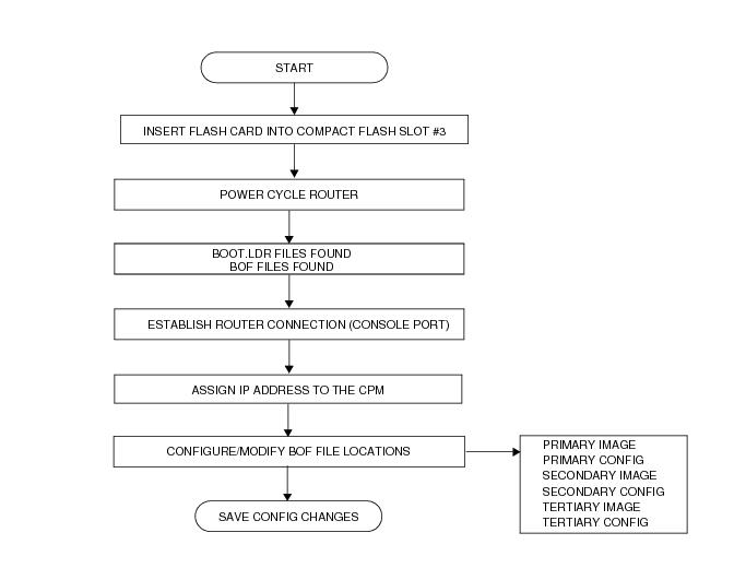
Starting a 7750 SR-Seriesrouter begins with hardware initialization (a reset or power cycle). By default, the system searches Compact Flash Slot #3 (cf3) for the boot.ldr file (also known as the bootstrap file). The boot.ldr file is the image that reads and executes the system initialization commands configured in the boot option file (BOF). The default value to initially search for the boot.ldr file on cf3 cannot be modified.
The following is an example of console display output when the boot.ldr file cannot be located on cf3.
... 
(memory test messages) 
(serial number information) 
Searching for boot.ldr on local drives:
No disk in cf3
No disk in cf3
No disk in cf3
Error - file boot.ldr not found on any drive
Please insert CF containing boot.ldr. Rebooting in 5 seconds.
When the bootstrap image is loaded, the BOF is read to obtain the location of the image and configuration files. The BOF must be located on the same compact flash drive as the boot.ldr file.
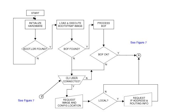
Figure 6 displays the system initialization sequence.
Figure 6: System Initialization - Part 1
 
Figure 7 displays the compact flash directory structure and file names for the redundant chassis models.
Figure 7: Files on the Compact Flash
Files on the compact flash are:
m — Major release number
n — minor release number
Y: A — Alpha release
B — Beta release
M — Maintenance release
R — Released software
z — Version number
iom.tim — IOM image file
Figure 8 displays the compact flash directory structure and file names for the 1-slot models (non-redundant).
Figure 8: Files on the Compact Flash
Files on the compact flash are:
m — Major release number
n — Minor release number
Y: A — Alpha release
B — Beta release
M — Maintenance release
R — Released software
z — Version number
The 7750 SR-Series router includes a boot option for running the node in a FIPS-140-2 mode. This mode limits the use of cryptographic algorithms on the CPM to only those that are in accordance with the FIPS-140-2 certifications associated with the 7750 SR-Series router.
 
Configuration and Image Loading
When the system executes the boot.ldr file, the initialization parameters from the BOF are processed. Three locations can be configured for the system to search for the files that contains the runtime image. The locations can be local or remote. The first location searched is the primary image location. If not found, the secondary image location is searched, and lastly, the tertiary image location is searched.
If the BOF cannot be found or loaded, then the system enters a console message dialog session prompting the user to enter alternate file locations and file names.
The boot.ldr can be interrupted during the boot sequence by pressing any key on the CPM console port. The operator must then type sros and press ENTER within 30 seconds or the boot.ldr will continue trying to boot the system. This key sequence ensures that noise or misconfiguration does not inadvertently interrupt the boot sequence. If the operator types sros and presses ENTER within 30 seconds, they are brought to a console message dialog session prompting the user to enter file locations and other boot information.
When the runtime image is successfully loaded, control is passed from the bootstrap loader to the image. The runtime image attempts to locate the configuration file as configured in the BOF. Like the runtime image, three locations can be configured for the system to search for the configuration file. The locations can be local or remote. The first location searched is the primary configuration location. If not found, the secondary configuration location is searched, and lastly, the tertiary configuration location is searched. The configuration file include chassis, IOM, MDA, and port configurations, as well as system, routing, and service configurations.
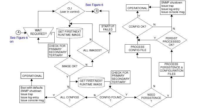
Figure 9 displays the boot sequence.
Figure 9: System Initialization - Part 2
The following displays an example of BOF output.
A:ALA-1>bof# show bof
==================================================================
Memory BOF
==================================================================
no autonegotiate
duplex      	full
speed      	100
address    	10.10.xx.xx/20 active
wait    	3
primary-image 	cf3:\both.tim
primary-config 	cf3:\test123.cfg
primary-dns 	192.168.xx.xx 
persist     	on
dns-domain 	test.alcatel.com
==================================================================
A:ALA-1>bof#
 
Persistence
Optionally, the BOF persist parameter can specify whether the system should preserve system indexes when a save command is executed. During a subsequent boot, the index file is read along with the configuration file. As a result, a number of system indexes are preserved between reboots, including the interface index, LSP IDs, path IDs, etc If persistence is not required and the configuration file is successfully processed, then the system becomes operational. If persist is required, then a matching x.ndx file must be located and successfully processed before the system can become operational. Matching files (configuration and index files) must have the same filename prefix such as test123.cfg and test123.ndx and are created at the same time when a save command is executed. Note that the persistence option must be enabled to deploy the Network Management System (NMS). The default is off.
Traps, logs, and console messages are generated if problems occur and SNMP shuts down for all SNMP gets and sets, however, traps are issued.
 
Lawful Intercept
Lawful Intercept (LI) describes a process to intercept telecommunications by which law enforcement authorities can un-obtrusively monitor voice and data communications to combat crime and terrorism with higher security standards of lawful intercept capabilities in accordance with local law and after following due process and receiving proper authorization from competent authorities. The interception capabilities are sought by various telecommunications providers.
As lawful interception is subject to national regulation, requirements vary from one country to another. Alcatel-Lucent’s implementation satisfies most national standard’s requirements. LI is configurable for all service types.
 
FIPS-140-2 Mode
The 7750 SR-Series router includes a configurable parameter in the bof.cfg file to make the node run in FIPS-140-2 mode. When the node boots in FIPS-140-2 mode, the following behaviors are enabled on the node:
To support FIPS-140-2, an HMAC-SHA-1 integrity check is performed to verify the integrity of the software images. The following file is included in the TIMOS-m.n.Yz software bundle containing the hmac-sha-1 signature:
During the loading of the cpm.tim or both.tim, a HMAC-SHA-1 check is performed to ensure that the calculated HMAC-SHA-1 of the loaded image matches that stored in the hmac-sha1.txt file.
The HMAC-SHA-1 check is performed on the data loaded from the .tim file. Note that when configuring the primary-image, secondary-image and tertiary-image, the hmac-sha1.txt file must exist in the same directory as the .tim files. If the load has been verified correctly from the HMAC-SHA-1 integrity check, the load continues to bootup as normal. If the load is not verified by the HMAC-SHA-1 integrity check, the image load will fail.
After the HMAC-SHA-1 integrity check passes, the nodes continues its normal bootup sequence including reading the config.cfg file and loading the configuration. The config.cfg file used to boot the node in FIPS-140-2 mode must not contain any configuration that is not supported in FIPS-140-2 mode. If such configuration is present in the config.cfg file when the node boots, the node will load the config.cfg file until the location of the offending configuration and then halt the configuration at that point. Upon a failure to load the config.cfg file, a failure message is printed on the console.
Initial System Startup Process Flow
Figure 10 displays the process start your system. Note that this example assumes that the boot loader and BOF image and configuration files are successfully located.
 
Figure 10: System Startup Flow
Configuration Notes
This section describes BOF configuration caveats.