For feedback, use the following:
ipd_online_feedback@alcatel-lucent.com
Table of Contents Previous Next Index PDF


Label Distribution Protocol
In This Chapter
This chapter provides information to enable Label Distribution Protocol (LDP).
Topics in this chapter include:
Label Distribution Protocol
Label Distribution Protocol (LDP) is a protocol used to distribute labels in non-traffic-engineered applications. LDP allows routers to establish label switched paths (LSPs) through a network by mapping network-layer routing information directly to data link layer-switched paths.
An LSP is defined by the set of labels from the ingress Label Switching Router (LSR) to the egress LSR. LDP associates a Forwarding Equivalence Class (FEC) with each LSP it creates. A FEC is a collection of common actions associated with a class of packets. When an LSR assigns a label to a FEC, it must let other LSRs in the path know about the label. LDP helps to establish the LSP by providing a set of procedures that LSRs can use to distribute labels.
The FEC associated with an LSP specifies which packets are mapped to that LSP. LSPs are extended through a network as each LSR splices incoming labels for a FEC to the outgoing label assigned to the next hop for the given FEC.
LDP allows an LSR to request a label from a downstream LSR so it can bind the label to a specific FEC. The downstream LSR responds to the request from the upstream LSR by sending the requested label.
LSRs can distribute a FEC label binding in response to an explicit request from another LSR. This is known as Downstream On Demand (DOD) label distribution. LSRs can also distribute label bindings to LSRs that have not explicitly requested them. This is called Downstream Unsolicited (DUS).
 
LDP and MPLS
LDP performs the label distribution only in MPLS environments. The LDP operation begins with a hello discovery process to find LDP peers in the network. LDP peers are two LSRs that use LDP to exchange label/FEC mapping information. An LDP session is created between LDP peers. A single LDP session allows each peer to learn the other's label mappings (LDP is bi-directional) and to exchange label binding information.
LDP signaling works with the MPLS label manager to manage the relationships between labels and the corresponding FEC. For service-based FECs, LDP works in tandem with the Service Manager to identify the virtual leased lines (VLLs) and Virtual Private LAN Services (VPLSs) to signal.
An MPLS label identifies a set of actions that the forwarding plane performs on an incoming packet before discarding it. The FEC is identified through the signaling protocol (in this case, LDP) and allocated a label. The mapping between the label and the FEC is communicated to the forwarding plane. In order for this processing on the packet to occur at high speeds, optimized tables are maintained in the forwarding plane that enable fast access and packet identification.
When an unlabeled packet ingresses the router, classification policies associate it with a FEC. The appropriate label is imposed on the packet, and the packet is forwarded. Other actions that can take place before a packet is forwarded are imposing additional labels, other encapsulations, learning actions, etc. When all actions associated with the packet are completed, the packet is forwarded.
When a labeled packet ingresses the router, the label or stack of labels indicates the set of actions associated with the FEC for that label or label stack. The actions are preformed on the packet and then the packet is forwarded.
The LDP implementation provides DOD, DUS, ordered control, liberal label retention mode support.
 
LDP Architecture
LDP comprises a few processes that handle the protocol PDU transmission, timer-related issues, and protocol state machine. The number of processes is kept to a minimum to simplify the architecture and to allow for scalability. Scheduling within each process prevents starvation of any particular LDP session, while buffering alleviates TCP-related congestion issues.
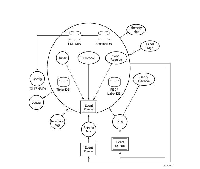
The LDP subsystems and their relationships to other subsystems are illustrated in Figure 34. This illustration shows the interaction of the LDP subsystem with other subsystems, including memory management, label management, service management, SNMP, interface management, and RTM. In addition, debugging capabilities are provided through the logger.
Communication within LDP tasks is typically done by inter-process communication through the event queue, as well as through updates to the various data structures. The primary data structures that LDP maintains are:
 
Subsystem Interrelationships
The sections below describe how LDP and the other subsystems work to provide services.
Figure 34: Subsystem Interrelationships
 
Memory Manager and LDP
LDP does not use any memory until it is instantiated. It pre-allocates some amount of fixed memory so that initial startup actions can be performed. Memory allocation for LDP comes out of a pool reserved for LDP that can grow dynamically as needed. Fragmentation is minimized by allocating memory in larger chunks and managing the memory internally to LDP. When LDP is shut down, it releases all memory allocated to it.
 
Label Manager
LDP assumes that the label manager is up and running. LDP will abort initialization if the label manager is not running. The label manager is initialized at system boot-up; hence, anything that causes it to fail will likely imply that the system is not functional. The router uses a label range from 28672 (28K) to 131071 (128K-1) to allocate all dynamic labels, including RSVP allocated labels and VC labels.
 
LDP Configuration
The router uses a single consistent interface to configure all protocols and services. CLI commands are translated to SNMP requests and are handled through an agent-LDP interface. LDP can be instantiated or deleted through SNMP. Also, LDP targeted sessions can be set up to specific endpoints. Targeted-session parameters are configurable.
 
Logger
LDP uses the logger interface to generate debug information relating to session setup and teardown, LDP events, label exchanges, and packet dumps. Per-session tracing can be performed.
 
Service Manager
All interaction occurs between LDP and the service manager, since LDP is used primarily to exchange labels for Layer 2 services. In this context, the service manager informs LDP when an LDP session is to be set up or torn down, and when labels are to be exchanged or withdrawn. In turn, LDP informs service manager of relevant LDP events, such as connection setups and failures, timeouts, labels signaled/withdrawn.
 
Execution Flow
LDP activity in the operating system is limited to service-related signaling. Therefore, the configurable parameters are restricted to system-wide parameters, such as hello and keepalive timeouts.
 
Initialization
MPLS must be enabled when LDP is initialized. LDP makes sure that the various prerequisites, such as ensuring the system IP interface is operational, the label manager is operational, and there is memory available, are met. It then allocates itself a pool of memory and initializes its databases.
 
Session Lifetime
In order for a targeted LDP (T-LDP) session to be established, an adjacency must be created. The LDP extended discovery mechanism requires hello messages to be exchanged between two peers for session establishment. After the adjacency establishment, session setup is attempted.
 
Adjacency Establishment
In the router, the adjacency management is done through the establishment of a Service Distribution Path (SDP) object, which is a service entity in the Alcatel-Lucent service model.
The Alcatel-Lucent service model uses logical entities that interact to provide a service. The service model requires the service provider to create configurations for four main entities:
An SDP is the network-side termination point for a tunnel to a remote router. An SDP defines a local entity that includes the system IP address of the remote routers and a path type. Each SDP comprises:
If the SDP is identified as using LDP signaling, then an LDP extended hello adjacency is attempted.
If another SDP is created to the same remote destination, and if LDP signaling is enabled, no further action is taken, since only one adjacency and one LDP session exists between the pair of nodes.
An SDP is a uni-directional object, so a pair of SDPs pointing at each other must be configured in order for an LDP adjacency to be established. Once an adjacency is established, it is maintained through periodic hello messages.
 
Session Establishment
When the LDP adjacency is established, the session setup follows as per the LDP specification. Initialization and keepalive messages complete the session setup, followed by address messages to exchange all interface IP addresses. Periodic keepalives or other session messages maintain the session liveliness.
Since TCP is back-pressured by the receiver, it is necessary to be able to push that back-pressure all the way into the protocol. Packets that cannot be sent are buffered on the session object and re-attempted as the back-pressure eases.
 
Label Exchange
Label exchange is initiated by the service manager. When an SDP is attached to a service (for example, the service gets a transport tunnel), a message is sent from the service manager to LDP. This causes a label mapping message to be sent. Additionally, when the SDP binding is removed from the service, the VC label is withdrawn. The peer must send a label release to confirm that the label is not in use.
 
Other Reasons for Label Actions
Other reasons for label actions include:
 
Cleanup
LDP closes all sockets, frees all memory, and shuts down all its tasks when it is deleted, so its memory usage is 0 when it is not running.
 
Configuring Implicit Null Label
The implicit null label option allows an egress LER to receive MPLS packets from the previous hop without the outer LSP label. The user can configure to signal the implicit operation of the previous hop is referred to as penultimate hop popping (PHP). This option is signaled by the egress LER to the previous hop during the FEC signaling by the LDP control protocol.
t null option for all LDP FECs for which this node is the egress LER using the following command:
config>router>ldp>implicit-null-label
When the user changes the implicit null configuration option, LDP withdraws all the FECs and re-advertises them using the new label value.
 
Global LDP Filters
Both inbound and outbound LDP label binding filtering are supported.
Inbound filtering is performed by way of the configuration of an import policy to control the label bindings an LSR accepts from its peers. Label bindings can be filtered based on:
The default import policy is to accept all FECs received from peers.
Outbound filtering is performed by way of the configuration of an export policy. The Global LDP export policy can be used to explicitly originate label bindings for local interfaces. The Global LDP export policy does not filter out or stop propagation of any FEC received from neighbors. Use the LDP peer export prefix policy for this purpose. It must also be noted that the system IP address AND static FECs cannot be blocked using an export policy.
Export policy enables configuration of a policy to advertise label bindings based on:
The default export policy is to originate label bindings for system address only and to propagate all FECs received from other LDP peers.
Finally, it must be noted that the 'neighbor' statement inside a global import or export policy is not considered by LDP. Use the LDP peer import or export prefix policy for this purpose.
 
Per LDP Peer FEC Import and Export Policies
The FEC prefix export policy provides a way to control which FEC prefixes received from prefixes received from other LDP and T-LDP peers are re-distributed to this LDP peer.
The user configures the FEC prefix export policy using the following command:
config>router>ldp>peer-parameters>peer>export-prefixes policy-name
By default, all FEC prefixes are exported to this peer.
The FEC prefix import policy provides a mean of controlling which FEC prefixes received from this LDP peer are imported and installed by LDP on this node. If resolved these FEC prefixes are then re-distributed to other LDP and T-LDP peers.
The user configures the FEC prefix export policy using the following command:
config>router>ldp>peer-parameters>peer>import-prefixes policy-name
By default, all FEC prefixes are imported from this peer.
 
Configuring Multiple LDP LSR ID
The multiple LDP LSR-ID feature provides the ability to configure and initiate multiple Targeted LDP (T-LDP) sessions on the same system using different LDP LSR-IDs. In the current implementation, all T-LDP sessions must have the LSR-ID match the system interface address. This feature continues to allow the use of the system interface by default, but also any other network interface, including a loopback, address on a per T-LDP session basis. Note that LDP control plane will not allow more than a single T-LDP session with different local LSR ID values to the same LSR-ID in a remote node.
An SDP of type LDP can use a provisioned targeted session with the local LSR-ID set to any network IP for the T-LDP session to the peer matching the SDP far-end address. If, however, no targeted session has been explicitly pre-provisioned to the far-end node under LDP, then the SDP will auto-establish one but will use the system interface address as the local LSR-ID.
An SDP of type RSVP must use an RSVP LSP with the destination address matching the remote node LDP LSR-ID. An SDP of type GRE can only use a T-LDP session with a local LSR-ID set to the system interface.
The multiple LDP LSR-ID feature also provides the ability to use the address of the local LDP interface, or any other network IP interface configured on the system, as the LSR-ID to establish link LDP Hello adjacency and LDP session with directly connected LDP peers. The network interface can be a loopback or not.
Link LDP sessions to all peers discovered over a given LDP interface share the same local LSR-ID. However, LDP sessions on different LDP interfaces can use different network interface addresses as their local LSR-ID.
By default, the link and targeted LDP sessions to a peer use the system interface address as the LSR-ID unless explicitly configured using this feature. Note, however, that the system interface must always be configured on the router or the LDP protocol will not come up on the node. There is no requirement to include it in any routing protocol.
Note that when an interface other than system is used as the LSR-ID, the transport connection (TCP) for the link or targeted LDP session will also use the address of that interface as the transport address.
 
T-LDP hello reduction
This feature implements a new mechanism to suppress the transmission of the Hello messages following the establishment of a Targeted LDP session between two LDP peers. The Hello adjacency of the targeted session does not require periodic transmission of Hello messages as in the case of a link LDP session. In link LDP, one or more peers can be discovered over a given network IP interface and as such, the periodic transmission of Hello messages is required to discover new peers in addition to the periodic Keep-Alive message transmission to maintain the existing LDP sessions. A Targeted LDP session is established to a single peer. Thus, once the Hello Adjacency is established and the LDP session is brought up over a TCP connection, Keep-Alive messages are sufficient to maintain the LDP session.
When this feature is enabled, the targeted Hello adjacency is brought up by advertising the Hold-Time value the user configured in the Hello timeout parameter for the targeted session. The LSR node will then start advertising an exponentially increasing Hold-Time value in the Hello message as soon as the targeted LDP session to the peer is up. Each new incremented Hold-Time value is sent in a number of Hello messages equal to the value of the Hello reduction factor before the next exponential value is advertised. This provides time for the two peers to settle on the new value. When the Hold-Time reaches the maximum value of 0xffff (binary 65535), the two peers will stop sending Hello messages for the lifetime of the targeted LDP session.
Both LDP peers must be configured with this feature to bring gradually their advertised Hold-Time up to the maximum value. If one of the LDP peers does not, the frequency of the Hello messages of the targeted Hello adjacency will continue to be governed by the smaller of the two Hold-Time values. This feature complies to draft-pdutta-mpls-tldp-hello-reduce.
 
Tracking a T-LDP Peer with BFD
BFD tracking of an LDP session associated with a T-LDP adjacency allows for faster detection of the liveliness of the session by registering the transport address of a LDP session with a BFD session.
By enabling BFD for a selected targeted session, the state of that session is tied to the state of the underneath BFD session between the two nodes. The parameters used for the BFD are set with the BFD command under the IP interface.
 
Tracking a Link LDP Peer with BFD
Tracking of the Hello adjacency to an LDP peer using BFD is supported.
Hello adjacency tracking with BFD is enabled by enabling BFD on an LDP interface:
The parameters used for the BFD session, for example, transmit-interval, receive-interval, and multiplier, are those configured under the IP interface in the existing config>router>interface>bfd context.
When this command is enabled on an LDP interface, LDP registers with BFD and starts tracking the LSR-id of all peers it forms Hello adjacencies with over that LDP interface.
The parameters used for the BFD session, for example, transmit-interval, receive-interval, and multiplier, are those configured under the IP interface in the existing config>router>interface>bfd context.
When enabled, the LDP hello mechanism is used to determine the remote address to be used for the BFD session. If a BFD session fails, then the associated LDP adjacency is also declared down and LDP will immediately begin its reconvergence.
 
LDP LSP Statistics
RSVP-TE LSP statistics is extended to LDP to provide the following counters:
The counters are available for the egress data path of an LDP FEC at ingress LER and at LSR. Because an ingress LER is also potentially an LSR for an LDP FEC, combined egress data path statistics will be provided whenever applicable.
This feature is supported on IOM2-20g, IMM and IOM3-XP and requires chassis mode C or higher.
 
 
TTL Security for BGP and LDP
The BGP TTL Security Hack (BTSH) was originally designed to protect the BGP infrastructure from CPU utilization-based attacks. It is derived from the fact that the vast majority of ISP eBGP peerings are established between adjacent routers. Since TTL spoofing is considered nearly impossible, a mechanism based on an expected TTL value can provide a simple and reasonably robust defense from infrastructure attacks based on forged BGP packets.
While TTL Security Hack (TSH) is most effective in protecting directly connected peers, it can also provide a lower level of protection to multi-hop sessions. When a multi-hop BGP session is required, the expected TTL value can be set to 255 minus the configured range-of-hops. This approach can provide a qualitatively lower degree of security for BGP (such as a DoS attack could, theoretically, be launched by compromising a box in the path). However, BTSH will catch a vast majority of observed distributed DoS (DDoS) attacks against eBGP.
TSH can be used to protect LDP peering sessions as well. For details, see draft-chen-ldp-ttl-xx.txt, TTL-Based Security Option for LDP Hello Message.
The TSH implementation supports the ability to configure TTL security per BGP/LDP peer and evaluate (in hardware) the incoming TTL value against the configured TTL value. If the incoming TTL value is less than the configured TTL value, the packets are discarded and a log is generated.
 
ECMP Support for LDP
ECMP support for LDP performs load balancing for LDP based LSPs by having multiple outgoing next-hops for a given IP prefix on ingress and transit LSRs.
An LSR that has multiple equal cost paths to a given IP prefix can receive an LDP label mapping for this prefix from each of the downstream next-hop peers. As the LDP implementation uses the liberal label retention mode, it retains all the labels for an IP prefix received from multiple next-hop peers.
Without ECMP support for LDP, only one of these next-hop peers will be selected and installed in the forwarding plane. The algorithm used to determine the next-hop peer to be selected involves looking up the route information obtained from the RTM for this prefix and finding the first valid LDP next-hop peer (for example, the first neighbor in the RTM entry from which a label mapping was received). If, for some reason, the outgoing label to the installed next-hop is no longer valid, say the session to the peer is lost or the peer withdraws the label, a new valid LDP next-hop peer will be selected out of the existing next-hop peers and LDP will reprogram the forwarding plane to use the label sent by this peer.
With ECMP support, all the valid LDP next-hop peers, those that sent a label mapping for a given IP prefix, will be installed in the forwarding plane. In both cases, ingress LER and transit LSR, an ingress label will be mapped to the nexthops that are in the RTM and from which a valid mapping label has been received. The forwarding plane will then use an internal hashing algorithm to determine how the traffic will be distributed amongst these multiple next-hops, assigning each “flow” to a particular next-hop.
The hash algorithm at LER and transit LSR are described in the LAG and ECMP Hashing section of the 7750 SR OS Interface Guide.
 
Label Operations
If an LSR is the ingress for a given IP prefix, LDP programs a push operation for the prefix in the forwarding engine. This creates an LSP ID to the Next Hop Label Forwarding Entry (NHLFE) (LTN) mapping and an LDP tunnel entry in the forwarding plane. LDP will also inform the Tunnel Table Manager (TTM) of this tunnel. Both the LTN entry and the tunnel entry will have a NHLFE for the label mapping that the LSR received from each of its next-hop peers.
If the LSR is to behave as a transit for a given IP prefix, LDP will program a swap operation for the prefix in the forwarding engine. This involves creating an Incoming Label Map (ILM) entry in the forwarding plane. The ILM entry will have to map an incoming label to possibly multiple NHLFEs. If an LSR is an egress for a given IP prefix, LDP will program a POP entry in the forwarding engine. This too will result in an ILM entry being created in the forwarding plane but with no NHLFEs.
When unlabeled packets arrive at the ingress LER, the forwarding plane will consult the LTN entry and will use a hashing algorithm to map the packet to one of the NHLFEs (push label) and forward the packet to the corresponding next-hop peer. For labeled packets arriving at a transit or egress LSR, the forwarding plane will consult the ILM entry and either use a hashing algorithm to map it to one of the NHLFEs if they exist (swap label) or simply route the packet if there are no NHLFEs (pop label).
Static FEC swap will not be activated unless there is a matching route in system route table that also matches the user configured static FEC next-hop.
 
Unnumbered Interface Support in LDP
This feature allows LDP to establish Hello adjacency and to resolve unicast and multicast FECs over unnumbered LDP interfaces.
This feature also extends the support of lsp-ping, p2mp-lsp-ping, and ldp-treetrace to test an LDP unicast or multicast FEC which is resolved over an unnumbered LDP interface.
 
Feature Configuration
This feature does not introduce a new CLI command for adding an unnumbered interface into LDP.
Note however that the fec-originate command has been extended to specify the interface name since an unnumbered interface will not have an IP address of its own. The user can however specify the interface name for numbered interfaces too.
See the CLI section for the changes to the fec-originate command.
 
Operation of LDP over an Unnumbered IP Interface
Consider the setup shown in Figure 35.
Figure 35: LDP Adjacency and Session over Unnumbered Interface
LSR A and LSR B have the following LDP identifiers respectively:
<LSR Id=A> : <label space id=0>
<LSR Id=B> : <label space id=0>
There are two P2P unnumbered interfaces between LSR A and LSR B. These interfaces are identified on each system with their unique local link identifier. In other words, the combination of {Router-ID, Local Link Identifier} uniquely identifies the interface in OSPF or IS-IS throughout the network.
A borrowed IP address is also assigned to the interface to be used as the source address of IP packets which need to be originated from the interface. The borrowed IP address defaults to the system loopback interface address, A and B respectively in this setup. The user can change the borrowed IP interface to any configured IP interface, loopback or not, by applying the following command:
configure> router>interface>unnumbered [<ip-int-name| ip-address>]
When the unnumbered interface is added into LDP, it will have the following behavior.
 
Link LDP
Hello adjacency will be brought up using link Hello packet with source IP address set to the interface borrowed IP address and a destination IP address set to 224.0.0.2.
As a consequence of (1), Hello packets with the same source IP address should be accepted when received over parallel unnumbered interfaces from the same peer LSR-ID. The corresponding Hello adjacencies would be associated with a single LDP session.
The transport address for the TCP connection, which is encoded in the Hello packet, will always be set to the LSR-ID of the node regardless if the user enabled the interface option under configure>router>ldp>interface-parameters>interface>transport-address.
The user can configure the local-lsr-id option on the interface and change the value of the LSR-ID to either the local interface or to some other interface name, loopback or not, numbered or not. If the local interface is selected or the provided interface name corresponds to an unnumbered IP interface, the unnumbered interface borrowed IP address will be used as the LSR-ID. In all cases, the transport address for the LDP session will be updated to the new LSR-ID value but the link Hello packets will continue to use the interface borrowed IP address as the source IP address.
The LSR with the highest transport address, i.e., LSR-ID in this case, will bootstrap the TCP connection and LDP session.
Source and destination IP addresses of LDP packets are the transport addresses, i.e., LDP LSR-IDs of systems A and B in this case.
 
Targeted LDP
Source and destination addresses of targeted Hello packet are the LDP LSR-IDs of systems A and B.
The user can configure the local-lsr-id option on the targeted session and change the value of the LSR-ID to either the local interface or to some other interface name, loopback or not, numbered or not. If the local interface is selected or the provided interface name corresponds to an unnumbered IP interface, the unnumbered interface borrowed IP address will be used as the LSR-ID. In all cases, the transport address for the LDP session and the source IP address of targeted Hello message will be updated to the new LSR-ID value.
The LSR with the highest transport address, i.e., LSR-ID in this case, will bootstrap the TCP connection and LDP session.
Source and destination IP addresses of LDP messages are the transport addresses, i.e., LDP LSR-IDs of systems A and B in this case.
 
FEC Resolution
LDP will advertise/withdraw unnumbered interfaces using the Address/Address-Withdraw message. The borrowed IP address of the interface is used.
A FEC can be resolved to an unnumbered interface in the same way as it is resolved to a numbered interface. The outgoing interface and next-hop are looked up in RTM cache. The next-hop consists of the router-id and link identifier of the interface at the peer LSR.
LDP FEC ECMP next-hops over a mix of unnumbered and numbered interfaces is supported.
All LDP FEC types are supported.
The fec-originate command is supported when the next-hop is over an unnumbered interface.
All LDP features are supported except for the following:
 
 
LDP over RSVP Tunnels
LDP over RSVP-TE provides end-to-end tunnels that have two important properties, fast reroute and traffic engineering which are not available in LDP. LDP over RSVP-TE is focused at large networks (over 100 nodes in the network). Simply using end-to-end RSVP-TE tunnels will not scale. While an LER may not have that many tunnels, any transit node will potentially have thousands of LSPs, and if each transit node also has to deal with detours or bypass tunnels, this number can make the LSR overly burdened.
LDP over RSVP-TE allows tunneling of user packets using an LDP LSP inside an RSVP LSP.The main application of this feature is for deployment of MPLS based services, for example, VPRN, VLL, and VPLS services, in large scale networks across multiple IGP areas without requiring full mesh of RSVP LSPs between PE routers.
 
Figure 36: LDP over RSVP Application
The network displayed in Figure 36 consists of two metro areas, Area 1 and 2 respectively, and a core area, Area 3. Each area makes use of TE LSPs to provide connectivity between the edge routers. In order to enable services between PE1 and PE2 across the three areas, LSP1, LSP2, and LSP3 are set up using RSVP-TE. There are in fact 6 LSPs required for bidirectional operation but we will refer to each bi-directional LSP with a single name, for example, LSP1. A targeted LDP (T-LDP) session is associated with each of these bidirectional LSP tunnels. That is, a T-LDP adjacency is created between PE1 and ABR1 and is associated with LSP1 at each end. The same is done for the LSP tunnel between ABR1 and ABR2, and finally between ABR2 and PE2. The loopback address of each of these routers is advertised using T-LDP. Similarly, backup bidirectional LDP over RSVP tunnels, LSP1a and LSP2a, are configured by way of ABR3.
This setup effectively creates an end-to-end LDP connectivity which can be used by all PEs to provision services. The RSVP LSPs are used as a transport vehicle to carry the LDP packets from one area to another. Note that only the user packets are tunneled over the RSVP LSPs. The T-LDP control messages are still sent unlabeled using the IGP shortest path.
Note that in this application, the bi-directional RSVP LSP tunnels are not treated as IP interfaces and are not advertised back into the IGP. A PE must always rely on the IGP to look up the next hop for a service packet. LDP-over-RSVP introduces a new tunnel type, tunnel-in-tunnel, in addition to the existing LDP tunnel and RSVP tunnel types. If multiple tunnels types match the destination PE FEC lookup, LDP will prefer an LDP tunnel over an LDP-over-RSVP tunnel by default.
The design in Figure 36 allows a service provider to build and expand each area independently without requiring a full mesh of RSVP LSPs between PEs across the three areas.
In order to participate in a VPRN service, PE1 and PE2 perform the autobind to LDP. The LDP label which represents the target PE loopback address is used below the RSVP LSP label. Therefore a 3 label stack is required.
In order to provide a VLL service, PE1 and PE2 are still required to set up a targeted LDP session directly between them. Again a 3 label stack is required, the RSVP LSP label, followed by the LDP label for the loopback address of the destination PE, and finally the pseudowire label (VC label).
This implementation supports a variation of the application in Figure 36, in which area 1 is an LDP area. In that case, PE1 will push a two label stack while ABR1 will swap the LDP label and push the RSVP label as illustrated in Figure 37. LDP-over-RSVP tunnels can also be used as IGP shortcuts.
 
Figure 37: LDP over RSVP Application Variant
 
Signaling and Operation
 
LDP Label Distribution and FEC Resolution
The user creates a targeted LDP (T-LDP) session to an ABR or the destination PE. This results in LDP hellos being sent between the two routers. These messages are sent unlabeled over the IGP path. Next, the user enables LDP tunneling on this T-LDP session and optionally specifies a list of LSP names to associate with this T-LDP session. By default, all RSVP LSPs which terminate on the T-LDP peer are candidates for LDP-over-RSVP tunnels. At this point in time, the LDP FECs resolving to RSVP LSPs are added into the Tunnel Table Manager as tunnel-in-tunnel type.
Note that if LDP is running on regular interfaces also, then the prefixes LDP learns are going to be distributed over both the T-LDP session as well as regular IGP interfaces. The policy controls which prefixes go over the T-LDP session, for example, only /32 prefixes, or a particular prefix range.
LDP-over-RSVP works with both OSPF and ISIS. These protocols include the advertising router when adding an entry to the RTM. LDP-over-RSVP tunnels can be used as shortcuts for BGP next-hop resolution.
 
Default FEC Resolution Procedure
When LDP tries to resolve a prefix received over a T-LDP session, it performs a lookup in the Routing Table Manager (RTM). This lookup returns the next hop to the destination PE and the advertising router (ABR or destination PE itself). If the next-hop router advertised the same FEC over link-level LDP, LDP will prefer the LDP tunnel by default unless the user explicitly changed the default preference using the system wide prefer-tunnel-in-tunnel command. If the LDP tunnel becomes unavailable, LDP will select an LDP-over-RSVP tunnel if available.
When searching for an LDP-over-RSVP tunnel, LDP selects the advertising router(s) with best route. If the advertising router matches the T-LDP peer, LDP then performs a second lookup for the advertising router in the Tunnel Table Manager (TTM) which returns the user configured RSVP LSP with the best metric. If there are more than one configured LSP with the best metric, LDP selects the first available LSP.
If all user configured RSVP LSPs are down, no more action is taken. If the user did not configure any LSPs under the T-LDP session, the lookup in TTM will return the first available RSVP LSP which terminates on the advertising router with the lowest metric.
 
FEC Resolution Procedure When prefer-tunnel-in-tunnel is Enabled
When LDP tries to resolve a prefix received over a T-LDP session, it performs a lookup in the Routing Table Manager (RTM). This lookup returns the next hop to the destination PE and the advertising router (ABR or destination PE itself).
When searching for an LDP-over-RSVP tunnel, LDP selects the advertising router(s) with best route. If the advertising router matches the targeted LDP peer, LDP then performs a second lookup for the advertising router in the Tunnel Table Manager (TTM) which returns the user configured RSVP LSP with the best metric. If there are more than one configured LSP with the best metric, LDP selects the first available LSP.
If all user configured RSVP LSPs are down, then an LDP tunnel will be selected if available.
If the user did not configure any LSPs under the T-LDP session, a lookup in TTM will return the first available RSVP LSP which terminates on the advertising router. If none are available, then an LDP tunnel will be selected if available.
 
Rerouting Around Failures
Every failure in the network can be protected against, except for the ingress and egress PEs. All other constructs have protection available. These constructs are LDP-over-RSVP tunnel and ABR.
 
LDP-over-RSVP Tunnel Protection
An RSVP LSP can deal with a failure in two ways.
If the LSP is a CSPF-computed LSP with the fast reroute option enabled, then RSVP will switch to the detour path very quickly. From that point, a new LSP will be attempted from the head-end (global revertive). When the new LSP is in place, the traffic switches over to the new LSP with make-before-break.
 
ABR Protection
If an ABR fails, then routing around the ABR requires that a new next-hop LDP-over-RSVP tunnel be found to a backup ABR. If an ABR fails, then the T-LDP adjacency fails. Eventually, the backup ABR becomes the new next hop (after SPF converges), and LDP learns of the new next-hop and can reprogram the new path.
 
LDP over RSVP Without Area Boundary
The LDP over RSVP capability set includes the ability to stitch LDP-over-RSVP tunnels at internal (non-ABR) OSPF and IS-IS routers.
Figure 38: LDP over RSVP Without ABR Stitching Point
In Figure 38, assume that the user wants to use LDP over RSVP between router A and destination “Dest”. The first thing that happens is that either OSPF or IS-IS will perform an SPF calculation resulting in an SPF tree. This tree specifies the lowest possible cost to the destination. In the example shown, the destination “Dest” is reachable at the lowest cost through router X. The SPF tree will have the following path: A>C>E>G>X.
Using this SPF tree, router A will search for the endpoint that is closest (farthest/highest cost from the origin) to “Dest” that is eligible. Assuming that all LSPs in the above diagram are eligible, LSP endpoint G will be selected as it terminates on router G while other LSPs only reach routers C and E, respectively.
IGP and LSP metrics associated with the various LSP are ignores; only tunnel endpoint matters to IGP. The endpoint that terminates closest to “Dest” (highest IGP path cost) will be selected for further selection of the LDP over RSVP tunnels to that endpoint. Note that the explicit path the tunnel takes may not match the IGP path the SPF computes.
If router A and G have an additional LSP terminating on router G, there would now be two tunnels both terminating on the same router closest to the final destination. For IGP, it does not make any difference on the numbers of LDPs to G, only that there is at least one LSP to G. In this case, the LSP metric will be considered by LDP when deciding which LSP to stitch for the LDP over RSVP connection.
The IGP only passes endpoint information to LDP. LDP looks up the tunnel table for all tunnels to that endpoint and picks up the one with the least tunnel metric. There may be many tunnels with the same least cost.
 
LDP over RSVP and ECMP
ECMP for LDP over RSVP is supported (also see ECMP Support for LDP). If ECMP applies, all LSP endpoints found over the ECMP IGP path will be installed in the routing table by the IGP for consideration by LDP. It is important to note that IGP costs to each endpoint may differ because IGP selects the farthest endpoint per ECMP path.
LDP will choose the endpoint that is highest cost in the route entry and will do further tunnel selection over those endpoints. If there are multiple endpoints with equal highest cost, then LDP will consider all of them.
 
LDP Fast-Reroute for IS-IS and OSPF Prefixes
LDP Fast Re-Route (FRR) is a feature which allows the user to provide local protection for an LDP FEC by pre-computing and downloading to IOM both a primary and a backup NHLFE for this FEC.
The primary NHLFE corresponds to the label of the FEC received from the primary next-hop as per standard LDP resolution of the FEC prefix in RTM. The backup NHLFE corresponds to the label received for the same FEC from a Loop-Free Alternate (LFA) next-hop.
The LFA next-hop pre-computation by IGP is described in RFC 5286 – “Basic Specification for IP Fast Reroute: Loop-Free Alternates”. LDP FRR relies on using the label-FEC binding received from the LFA next-hop to forward traffic for a given prefix as soon as the primary next-hop is not available. This means that a node resumes forwarding LDP packets to a destination prefix without waiting for the routing convergence. The label-FEC binding is received from the loop-free alternate next-hop ahead of time and is stored in the Label Information Base since LDP on the router operates in the liberal retention mode.
This feature requires that IGP performs the Shortest Path First (SPF) computation of an LFA next-hop, in addition to the primary next-hop, for all prefixes used by LDP to resolve FECs. IGP also populates both routes in the Routing Table Manager (RTM).
 
LDP FRR Configuration
The user enables Loop-Free Alternate (LFA) computation by SPF under the IS-IS or OSPF routing protocol level:
config>router>isis>loopfree-alternate
config
>router>ospf>loopfree-alternate.
The above commands instruct the IGP SPF to attempt to pre-compute both a primary next-hop and an LFA next-hop for every learned prefix. When found, the LFA next-hop is populated into the RTM along with the primary next-hop for the prefix.
Next the user enables the use by LDP of the LFA next-hop by configuring the following option:
config>router>ldp>fast-reroute
When this command is enabled, LDP will use both the primary next-hop and LFA next-hop, when available, for resolving the next-hop of an LDP FEC against the corresponding prefix in the RTM. This will result in LDP programming a primary NHLFE and a backup NHLFE into the IOM for each next-hop of a FEC prefix for the purpose of forwarding packets over the LDP FEC.
Note that because LDP can detect the loss of a neighbor/next-hop independently, it is possible that it switches to the LFA next-hop while IGP is still using the primary next-hop. In order to avoid this situation, it is recommended to enable IGP-LDP synchronization on the LDP interface:
config>router>interface>ldp-sync-timer seconds
 
Reducing the Scope of the LFA Calculation by SPF
The user can instruct IGP to not include all interfaces participating in a specific IS-IS level or OSPF area in the SPF LFA computation. This provides a way of reducing the LFA SPF calculation where it is not needed.
config>router>isis>level>loopfree-alternate-exclude
config
>router>ospf>area>loopfree-alternate-exclude
Note that if IGP shortcut are also enabled in LFA SPF, as explained in Section 5.3.2, LSPs with destination address in that IS-IS level or OSPF area are also not included in the LFA SPF calculation.
The user can also exclude a specific IP interface from being included in the LFA SPF computation by IS-IS or OSPF:
config>router>isis>interface> loopfree-alternate-exclude
config
>router>ospf>area>interface> loopfree-alternate-exclude
Note that when an interface is excluded from the LFA SPF in IS-IS, it is excluded in both level 1 and level 2. When the user excludes an interface from the LFA SPF in OSPF, it is excluded in all areas. However, the above OSPF command can only be executed under the area in which the specified interface is primary and once enabled, the interface is excluded in that area and in all other areas where the interface is secondary. If the user attempts to apply it to an area where the interface is secondary, the command will fail.
Finally, the user can apply the same above commands for an OSPF instance within a VPRN service:
config>service>vprn>ospf>area>loopfree-alternate-exclude
config
>service>vprn>ospf>area>interface>loopfree-alternate-exclude
 
LDP FRR Procedures
The LDP FEC resolution when LDP FRR is not enabled operates as follows. When LDP receives a FEC, label binding for a prefix, it will resolve it by checking if the exact prefix, or a longest match prefix when the aggregate-prefix-match option is enabled in LDP, exists in the routing table and is resolved against a next-hop which is an address belonging to the LDP peer which advertized the binding, as identified by its LSR-id. When the next-hop is no longer available, LDP de-activates the FEC and de-programs the NHLFE in the data path. LDP will also immediately withdraw the labels it advertised for this FEC and deletes the ILM in the data path unless the user configured the label-withdrawal-delay option to delay this operation. Traffic that is received while the ILM is still in the data path is dropped. When routing computes and populates the routing table with a new next-hop for the prefix, LDP resolves again the FEC and programs the data path accordingly.
When LDP FRR is enabled and an LFA backup next-hop exists for the FEC prefix in RTM, or for the longest prefix the FEC prefix matches to when aggregate-prefix-match option is enabled in LDP, LDP will resolve the FEC as above but will program the data path with both a primary NHLFE and a backup NHLFE for each next-hop of the FEC.
In order perform a switchover to the backup NHLFE in the fast path, LDP follows the uniform FRR failover procedures which are also supported with RSVP FRR.
When any of the following events occurs, LDP instructs in the fast path the IOM to enable the backup NHLFE for each FEC next-hop impacted by this event. The IOM do that by simply flipping a single state bit associated with the failed interface or neighbor/next-hop:
1.
2.
3.
4.
5.
A BFD session enabled on the LDP interface to a directly connected peer, times-out and brings down the link LDP session to this peer. In this case, LDP sends a neighbor/next-hop down message to the IOM for this LDP peer only. BFD support on LDP interfaces is a new feature introduced for faster tracking of link LDP peers. See Section 1.2.1 for more details.
The tunnel-down-dump-time option or the label-withdrawal-delay option, when enabled, does not cause the corresponding timer to be activated for a FEC as long as a backup NHLFE is still available.
 
Link LDP Hello Adjacency Tracking with BFD
LDP can only track an LDP peer with which it established a link LDP session with using the Hello and Keep-Alive timers. If an IGP protocol registered with BFD on an IP interface to track a neighbor, and the BFD session times out, the next-hop for prefixes advertised by the neighbor are no longer resolved. This however does not bring down the link LDP session to the peer since the LDP peer is not directly tracked by BFD. More importantly the LSR-id of the LDP peer may not coincide with the neighbor’s router-id IGP is tracking by way of BFD.
In order to properly track the link LDP peer, LDP needs to track the Hello adjacency to its peer by registering with BFD. This way, the peer next-hop is tracked.
The user enables Hello adjacency tracking with BFD by enabling BFD on an LDP interface:
config>router>ldp>interface-parameters>interface>enable-bfd
The parameters used for the BFD session, i.e., transmit-interval, receive-interval, and multiplier, are those configured under the IP interface in existing implementation:
config>router>interface>bfd
When multiple links exist to the same LDP peer, a Hello adjacency is established over each link but only a single LDP session will exist to the peer and will use a TCP connection over one of the link interfaces. Also, a separate BFD session should be enabled on each LDP interface. If a BFD session times out on a specific link, LDP will immediately bring down the Hello adjacency on that link. In addition, if the there are FECs which have their primary NHLFE over this link, LDP triggers the LDP FRR procedures by sending to IOM the neighbor/next-hop down message. This will result in moving the traffic of the impacted FECs to an LFA next-hop on a different link to the same LDP peer or to an LFA backup next-hop on a different LDP peer depending on the lowest backup cost path selected by the IGP SPF.
As soon as the last Hello adjacency goes down due to BFD timing out, the LDP session goes down and the LDP FRR procedures will be triggered. This will result in moving the traffic to an LFA backup next-hop on a different LDP peer.
 
ECMP Considerations
Whenever the SPF computation determined there is more than one primary next-hop for a prefix, it will not program any LFA next-hop in RTM. Thus, the LDP FEC will resolve to the multiple primary next-hops in this case which provides the required protection.
Also note that when the system ECMP value is set to ecmp=1 or to no ecmp, which translates to the same and is the default value, SPF will be able to use the overflow ECMP links as LFA next-hops in these two cases.
 
LDP FRR and LDP Shortcut
When LDP FRR is enabled in LDP and the ldp-shortcut option is enabled in the router level, in transit IPv4 packets and specific CPM generated IPv4 control plane packets with a prefix resolving to the LDP shortcut are protected by the backup LDP NHLFE.
 
LDP FRR and LDP-over-RSVP
When LDP-over-RSVP is enabled, the RSVP LSP is modeled as an endpoint, i.e., the destination node of the LSP, and not as a link in the IGP SPF. Thus, it is not possible for IGP to compute a primary or alternate next-hop for a prefix which FEC path is tunneled over the RSVP LSP. Only LDP is aware of the FEC tunneling but it cannot determine on its own a loop-free backup path when it resolves the FEC to an RSVP LSP.
As a result, LDP does not activate the LFA next-hop it learned from RTM for a FEC prefix when the FEC is resolved to an RSVP LSP. LDP will activate the LFA next-hop as soon as the FEC is resolved to direct primary next-hop.
LDP FEC tunneled over an RSVP LSP due to enabling the LDP-over-RSVP feature will thus not support the LDP FRR procedures and will follow the slow path procedure of prior implementation.
Note that when the user enables the lfa-only option for an RSVP LSP, as described in Loop-Free Alternate Calculation in the Presence of IGP shortcuts, such an LSP will not be used by LDP to tunnel an LDP FEC even when IGP shortcut is disabled but LDP-over-RSVP is enabled in IGP.
 
LDP FRR and RSVP Shortcut (IGP Shortcut)
When an RSVP LSP is used as a shortcut by IGP, it is included by SPF as a P2P link and can also be optionally advertised into the rest of the network by IGP. Thus the SPF is able of using a tunneled next-hop as the primary next-hop for a given prefix. LDP is also able of resolving a FEC to a tunneled next-hop when the IGP shortcut feature is enabled.
When both IGP shortcut and LFA are enabled in IS-IS or OSPF, and LDP FRR is also enabled, then the following additional LDP FRR capabilities are supported:
1.
2.
The LFA SPF is extended to use IGP shortcuts as LFA next-hops as explained in Loop-Free Alternate Calculation in the Presence of IGP shortcuts.
 
IS-IS and OSPF Support for Loop-Free Alternate Calculation
SPF computation in IS-IS and OSPF is enhanced to compute LFA alternate routes for each learned prefix and populate it in RTM.
Figure 39 illustrates a simple network topology with point-to-point (P2P) interfaces and highlights three routes to reach router R5 from router R1.
Figure 39: Topology with Primary and LFA Routes
The primary route is by way of R3. The LFA route by way of R2 has two equal cost paths to reach R5. The path by way of R3 protects against failure of link R1-R3. This route is computed by R1 by checking that the cost for R2 to reach R5 by way of R3 is lower than the cost by way of routes R1 and R3. This condition is referred to as the loop-free criterion. R2 must be loop-free with respect to source node R1.
The path by way of R2 and R4 can be used to protect against the failure of router R3. However, with the link R2-R3 metric set to 5, R2 sees the same cost to forward a packet to R5 by way of R3 and R4. Thus R1 cannot guarantee that enabling the LFA next-hop R2 will protect against R3 node failure. This means that the LFA next-hop R2 provides link-protection only for prefix R5. If the metric of link R2-R3 is changed to 8, then the LFA next-hop R2 provides node protection since a packet to R5 will always go over R4. In other words it is required that R2 becomes loop-free with respect to both the source node R1 and the protected node R3.
Consider the case where the primary next-hop uses a broadcast interface as illustrated in Figure 40
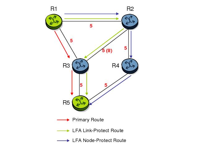
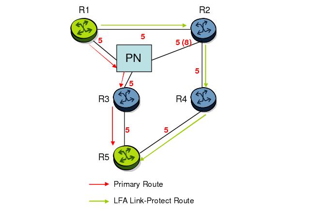
Figure 40: Example Topology with Broadcast Interfaces
In order for next-hop R2 to be a link-protect LFA for route R5 from R1, it must be loop-free with respect to the R1-R3 link’s Pseudo-Node (PN). However, since R2 has also a link to that PN, its cost to reach R5 by way of the PN or router R4 are the same. Thus R1 cannot guarantee that enabling the LFA next-hop R2 will protect against a failure impacting link R1-PN since this may cause the entire subnet represented by the PN to go down. If the metric of link R2-PN is changed to 8, then R2 next-hop will be an LFA providing link protection.
The following are the detailed rules for this criterion as provided in RFC 5286:
Rule 1: Link-protect LFA backup next-hop (primary next-hop R1-R3 is a P2P interface):
Distance_opt(R2, R5) < Distance_opt(R2, R1) + Distance_opt(R1, R5)
and,
Distance_opt(R2, R5) >= Distance_opt(R2, R3) + Distance_opt(R3, R5)
Rule 2: Node-protect LFA backup next-hop (primary next-hop R1-R3 is a P2P interface):
Distance_opt(R2, R5) < Distance_opt(R2, R1) + Distance_opt(R1, R5)
and,
Distance_opt(R2, R5) < Distance_opt(R2, R3) + Distance_opt(R3, R5)
Rule 3: Link-protect LFA backup next-hop (primary next-hop R1-R3 is a broadcast interface):
Distance_opt(R2, R5) < Distance_opt(R2, R1) + Distance_opt(R1, R5)
and,
Distance_opt(R2, R5) < Distance_opt(R2, PN) + Distance_opt(PN, R5)
where; PN stands for the R1-R3 link Pseudo-Node.
For the case of P2P interface, if SPF finds multiple LFA next-hops for a given primary next-hop, it follows the following selection algorithm:
A)
B)
C)
For the case of a broadcast interface, a node-protect LFA is not necessarily a link protect LFA if the path to the LFA next-hop goes over the same PN as the primary next-hop. Similarly, a link protect LFA may not guarantee link protection if it goes over the same PN as the primary next-hop.
The selection algorithm when SPF finds multiple LFA next-hops for a given primary next-hop is modified as follows:
A)
The first set consists of LFA next-hops which do not go over the PN used by primary next-hop.
The second set consists of LFA next-hops which do go over the PN used by the primary next-hop.
B)
C)
D)
E)
Note this algorithm is more flexible than strictly applying Rule 3 above; the link protect rule in the presence of a PN and specified in RFC 5286. A node-protect LFA which does not avoid the PN; does not guarantee link protection, can still be selected as a last resort. The same thing, a link-protect LFA which does not avoid the PN may still be selected as a last resort.Both the computed primary next-hop and LFA next-hop for a given prefix are programmed into RTM.
 
Loop-Free Alternate Calculation in the Presence of IGP shortcuts
In order to expand the coverage of the LFA backup protection in a network, RSVP LSP based IGP shortcuts can be placed selectively in parts of the network and be used as an LFA backup next-hop.
When IGP shortcut is enabled in IS-IS or OSPF on a given node, all RSVP LSP originating on this node and with a destination address matching the router-id of any other node in the network are included in the main SPF by default.
In order to limit the time it takes to compute the LFA SPF, the user must explicitly enable the use of an IGP shortcut as LFA backup next-hop using one of a couple of new optional argument for the existing LSP level IGP shortcut command:
config>router>mpls>lsp>igp-shortcut [lfa-protect | lfa-only]
The lfa-protect option allows an LSP to be included in both the main SPF and the LFA SPFs. For a given prefix, the LSP can be used either as a primary next-hop or as an LFA next-hop but not both. If the main SPF computation selected a tunneled primary next-hop for a prefix, the LFA SPF will not select an LFA next-hop for this prefix and the protection of this prefix will rely on the RSVP LSP FRR protection. If the main SPF computation selected a direct primary next-hop, then the LFA SPF will select an LFA next-hop for this prefix but will prefer a direct LFA next-hop over a tunneled LFA next-hop.
The lfa-only option allows an LSP to be included in the LFA SPFs only such that the introduction of IGP shortcuts does not impact the main SPF decision. For a given prefix, the main SPF always selects a direct primary next-hop. The LFA SPF will select a an LFA next-hop for this prefix but will prefer a direct LFA next-hop over a tunneled LFA next-hop.
Thus the selection algorithm in Section 1.3 when SPF finds multiple LFA next-hops for a given primary next-hop is modified as follows:
A)
B)
C)
D)
E)
F)
G)
H)
 
Loop-Free Alternate Calculation for Inter-Area/inter-Level Prefixes
When SPF resolves OSPF inter-area prefixes or IS-IS inter-level prefixes, it will compute an LFA backup next-hop to the same exit area/border router as used by the primary next-hop.
mLDP Fast Upstream Switchover
mLDP Fast Upstream Switchover allows a downstream LSR of an multicast LDP (mLDP) FEC to perform a fast switchover and source the traffic from another upstream LSR while IGP is converging due to a failure of the primary next-hop of the P2MP FEC. In a sense, it provides an upstream Fast-Reroute (FRR) capability for the mLDP packets. It does it at the expense of traffic duplication from two different upstream nodes into the node that performs the fast upstream switchover.
When this feature is enabled and LDP is resolving an mLDP FEC received from a downstream LSR, it checks if an Equal-Cost Multi-Path (ECMP) next-hop or a Loop-Free Alternate (LFA) next-hop exist to the root LSR node. If LDP finds one, it programs a primary ILM on the interface corresponding to the primary next-hop and a backup ILM on the interface corresponding to the ECMP or LFA next-hop. LDP then sends the corresponding labels to the upstream LSR nodes. In normal operation, the primary ILM accepts packets while the backup ILM drops them. If the node detects that the interface or the upstream LSR of the primary ILM is down, the backup ILM will then start accepting packets.
In order to make use of the ECMP next-hop, the user must configure the ECMP value in the system to at least two (2). In order to make use of the LFA next-hop, the user must enable LFA and IP FRR options under the IGP instance.


LDP FEC to BGP Label Route Stitching
The stitching of an LDP FEC to a BGP labeled route allows LDP capable PE devices to offer services to PE routers in other areas or domains without the need to support BGP labeled routes.
This feature is used in a large network to provide services across multiple areas or autonomous systems. Figure 41 shows a network with a core area and regional areas.
Figure 41: Application of LDP to BGP FEC Stitching
Specific /32 routes in a regional area are not redistributed into the core area. Therefore, only nodes within a regional area and the ABR nodes in the same area exchange LDP FECs. A PE router, for example, PE21, in a regional area learns the reachability of PE routers in other regional areas by way of RFC 3107 BGP labeled routes redistributed by the remote ABR nodes by way of the core area. The remote ABR then sets the next-hop self on the labeled routes before re-distributing them into the core area. The local ABR for PE2, for example, ABR3 may or may not set next-hop self when it re-distributes these labeled BGP routes from the core area to the local regional area.
When forwarding a service packet to the remote PE, PE21 inserts a VC label, the BGP route label to reach the remote PE, and an LDP label to reach either ABR3, if ABR3 sets next-hop self, or ABR1.
In the same network, an MPLS capable DSLAM also act as PE router for VLL services and will need to establish a PW to a PE in a different regional area by way of router PE21, acting now as an LSR. To achieve that, PE21 is required to perform the following operations:
 
Configuration
The user enables the stitching of routes between LDP and BGP by configuring separately tunnel table route export policies in both protocols and enabling the advertising of RFC 3107 formatted labeled routes for prefixes learned from LDP FECs.
The route export policy in BGP instructs BGP to listen to LDP route entries in the CPM tunnel table. If a /32 LDP FEC prefix matches an entry in the export policy, BGP originates a BGP labeled route, stitches it to the LDP FEC, and re-distributes the BGP labeled route to its iBGP neighbors.
The user adds LDP FEC prefixes with the statement ‘from protocol ldp’ in the configuration of the existing BGP export policy at the global level, the peer-group level, or at the peer level using the commands:
 
To indicate to BGP to evaluate the entries with the ‘from protocol ldp’ statement in the export policy when applied to a specific BGP neighbor, a new argument is added to the existing advertise-label command:
configure>router>bgp>group>neighbour>advertise-label ipv4 include-ldp-prefix
Without the new include-ldp-prefix argument, only core IPv4 routes learned from RTM are advertised as BGP labeled routes to this neighbor. And the stitching of LDP FEC to the BGP labeled route is not performed for this neighbor even if the same prefix was learned from LDP.
The tunnel table route export policy in LDP instructs LDP to listen to BGP route entries in the CPM Tunnel Table. If a /32 BGP labeled route matches a prefix entry in the export policy, LDP originates an LDP FEC for the prefix, stitches it to the BGP labeled route, and re-distributes the LDP FEC its iBGP neighbors.
The user adds BGP labeled route prefixes with the statement ‘from protocol bgp’ in the configuration of a new LDP tunnel table export policy using the command:
configure>router>ldp>export-tunnel-table policy-name.
Note that the ‘from protocol’ statement has an effect only when the protocol value is ldp. Policy entries with protocol values of rsvp, bgp, or any value other than ldp are ignored at the time the policy is applied to LDP.
 
Detailed LDP FEC Resolution
When a 7x50 LSR receives a FEC-label binding from an LDP neighbor for a given specific FEC1 element, the following procedures are performed.
1.
2.
3.
 
Detailed BGP Labeled Route Resolution
When a 7x50 LSR receives a BGP labeled route by way of iBGP for a given specific /32 prefix, the following procedures are performed.
1.
2.
3.
 
Data Plane Forwarding
When a packet is received from an LDP neighbor, the 7x50 LSR swaps the LDP label into a BGP label and pushes the LDP label to reach the BGP neighbor, for example, ABR/ASBR, which advertised the BGP labeled route with itself as the next-hop.
When a packet is received from a BGP neighbor such as an ABR/ASBR, the top label is removed and the BGP label is swapped for the LDP label to reach the next-hop for the prefix.
 
Automatic Creation of a Targeted Hello Adjacency and LDP Session
This feature enables the automatic creation of a targeted Hello adjacency and LDP session to a discovered peer.
 
Feature Configuration
The user first creates a targeted LDP session peer parameter template:
config>router>ldp>targeted-session>peer-template template-name
Inside the template the user configures the common T-LDP session parameters or options shared by all peers using this template. These are the following:
bfd-enable, hello, hello-reduction, keepalive, local-lsr-id, and tunneling.
Note that the tunneling option does not support adding explicit RSVP LSP names. Thus, LDP will select RSVP LSP for an endpoint in LDP-over-RSVP directly from the Tunnel Table Manager (TTM).
Then the user references the peer prefix list which is defined inside a policy statement defined in the global policy manager.
config>router>ldp>targeted-session>peer-template-map peer-template template-name policy peer-prefix-policy
Each application of a targeted session template to a given prefix in the prefix list will result in the establishment of a targeted Hello adjacency to an LDP peer using the template parameters as long as the prefix corresponds to a router-id for a node in the TE database. The targeted Hello adjacency will either trigger a new LDP session or will be associated with an existing LDP session to that peer. See section 7.1.2 for more details on the behavior of this feature when an already active targeted Hello adjacency and LDP session exist to the peer.
Up to five (5) peer prefix policies can be associated with a single peer template at all times. Also, the user can associate multiple templates with the same or different peer prefix policies. Thus multiple templates can match with a given peer prefix. In all cases, the targeted session parameters applied to a given peer prefix are taken from the first created template by the user. This provides a more deterministic behavior regardless of the order in which the templates are associated with the prefix policies.
Each time the user executes the above command, with the same or different prefix policy associations, or the user changes a prefix policy associated with a targeted peer template, the system re-evaluates the prefix policy. The outcome of the re-evaluation will tell LDP if an existing targeted Hello adjacency needs to be torn down or if an existing targeted Hello adjacency needs to have its parameters updated on the fly.
If a /32 prefix is added to (removed from) or if a prefix range is expanded (shrunk) in a prefix list associated with a targeted peer template, the same prefix policy re-evaluation described above is performed.
The template comes up in the no shutdown state and as such it takes effect immediately. Once a template is in use, the user can change any of the parameters on the fly without shutting down the template. In this case, all targeted Hello adjacencies are.
There is no overall chassis mode restrictions enforced with the auto-created T-LDP session feature. If the chassis-mode, network chassis-mode or IOM type requirements for an LDP feature are not met, the configuration of the corresponding command will not be allowed as in existing implementation.
 
Feature Behavior
Whether the prefix list contains one or more specific /32 addresses or a range of addresses, an external trigger is required to indicate to LDP to instantiate a targeted Hello adjacency to a node which address matches an entry in the prefix list. The objective of the feature is to provide an automatic creation of a T-LDP session to the same destination as an auto-created RSVP LSP to achieve automatic tunneling of LDP-over-RSVP. The external trigger is when the router with the matching address appears in the Traffic Engineering database. In the latter case, an external module monitoring the TE database for the peer prefixes provides the trigger to LDP. As a result of this, the user must enable the traffic-engineering option in ISIS or OSPF.
Each mapping of a targeted session peer parameter template to a policy prefix which exists in the TE database will result in LDP establishing a targeted Hello adjacency to this peer address using the targeted session parameters configured in the template. This Hello adjacency will then either get associated with an LDP session to the peer if one exists or it will trigger the establishment of a new targeted LDP session to the peer.
The SR OS supports multiple ways of establishing a targeted Hello adjacency to a peer LSR:
User configuration of the peer with the targeted session parameters inherited from the config>router>ldp>targeted-session in the top level context or explicitly configured for this peer in the config>router>ldp>targeted-session>peer context and which overrides the top level parameters shared by all targeted peers. Let us refer to the top level configuration context as the global context. Note that some parameters only exist in the global context and as such their value will always be inherited by all targeted peers regardless of which event triggered it.
User configuration of an SDP of any type to a peer with the signaling tldp option enabled (default configuration). In this case the targeted session parameter values are taken from the global context.
BGP shortcut (igp-shortcut ldp option in BGP),
IGP shortcut (rsvp-shortcut option in IGP),
LDP shortcut for IGP routes (ldp-shortcut option in router level),
static route LDP shortcut (ldp option in a static route),
VPRN service (autobind ldp option), and
Since the above triggering events can occur simultaneously or in any arbitrary order, the LDP code implements a priority handling mechanism in order to decide which event overrides the active targeted session parameters. The overriding trigger will become the owner of the targeted adjacency to a given peer and will be shown in ‘show router ldp peer’.
The table below summarizes the triggering events and the associated priority.
Manual configuration of SDP with signaling tldp option enabled (creator=service manager)
Triggering Event Automatic Creation of Targeted Hello Adjacency Active Targeted Adjacency Parameter Override Priority
Manual configuration of peer parameters (creator=manual) Yes 1
Mapping of targeted session template to prefix policy (creator=template) Yes 2
Manual configuration of SDP with signaling tldp option enabled (creator=service manager) Yes 3
PW template binding in BGP-AD VPLS (creator=service manager) Yes 3
PW template binding in FEC 129 VLL (creator=service manager) Yes 3
LDP-over-RSVP as a BGP/IGP/ LDP/Static shortcut No N/A
LDP-over-RSVP in VPRN auto-bind No N/A
LDP-over-RSVP in BGP Label Route resolution No N/A
Table 5 1 Targeted LDP Adjacency Triggering Events and Priority
Note that any parameter value change to an active targeted Hello adjacency caused by any of the above triggering events is performed on the fly by having LDP immediately send a Hello message with the new parameters to the peer without waiting for the next scheduled time for the Hello message. This allows the peer to adjust its local state machine immediately and maintains both the Hello adjacency and the LDP session in UP state. The only exceptions are the following:
The triggering event caused a change to the local-lsr-id parameter value. In this case, the Hello adjacency is brought down which will also cause the LDP session to be brought down if this is the last Hello adjacency associated with the session. A new Hello adjacency and LDP session will then get established to the peer using the new value of the local LSR ID.
The triggering event caused the targeted peer shutdown option to be enabled. In this case, the Hello adjacency is brought down which will also cause the LDP session to be brought down if this is the last Hello adjacency associated with the session.
Finally, the value of any LDP parameter which is specific to the LDP/TCP session to a peer is inherited from the config>router>ldp>peer-parameters>peer context. This includes MD5 authentication, LDP prefix per-peer policies, label distribution mode (DU or DOD), etc.
 
 
Multicast P2MP LDP for GRT
P2MP LDP LSP setup is initiated by each leaf node of multicast tree. A leaf PE node learns to initiate a multicast tree setup from client application and sends a label map upstream towards the root node of the multicast tree. On propagation of label map, intermediate nodes that are common on path for multiple leaf nodes become branch nodes of the tree.
Figure 42 illustrates wholesale video distribution over P2MP LDP LSP. Static IGMP entries on edge are bound to P2MP LDP LSP tunnel-interface for multicast video traffic distribution.
Figure 42: Video Distribution using P2MP LDP
 
LDP P2MP Support
 
LDP P2MP Configuration
A node running LDP also supports P2MP LSP setup using LDP. By default, it would advertise the capability to a peer node using P2MP capability TLV in LDP initialization message.
This configuration option per interface is provided to restrict/allow the use of interface in LDP multicast traffic forwarding towards a downstream node. Interface configuration option does not restrict/allow exchange of P2MP FEC by way of established session to the peer on an interface, but it would only restrict/allow use of next-hops over the interface.
 
LDP P2MP Protocol
Only a single generic identifier range is defined for signaling multipoint tree for all client applications. Implementation on 7x50 SR reserves the range (1..8292) of generic LSP P2MP-ID on root node for static P2MP LSP.
 
Make Before Break (MBB)
When a transit or leaf node detects that the upstream node towards the root node of multicast tree has changed, it follows graceful procedure that allows make-before-break transition to the new upstream node. Make-before-break support is optional. If the new upstream node doe not support MBB procedures then the downstream node waits for the configured timer before switching over to the new upstream node.
 
ECMP Support
If multiple ECMP paths exist between two adjacent nodes then the upstream node of the multicast receiver programs all entries in forwarding plane. Only one entry is active based on ECMP hashing algorithm.
 
Multicast LDP Fast Upstream Switchover
This feature allows a downstream LSR of a multicast LDP (mLDP) FEC to perform a fast switchover and source the traffic from another upstream LSR while IGP and LDP are converging due to a failure of the upstream LSR which is the primary next-hop of the root LSR for the P2MP FEC. In essence it provides an upstream Fast-Reroute (FRR) node-protection capability for the mLDP FEC packets. It does it at the expense of traffic duplication from two different upstream nodes into the node which performs the fast upstream switchover.
The detailed procedures for this feature are described in draft-pdutta-mpls-mldp-up-redundancy.
 
Feature Configuration
The user enables the mLDP fast upstream switchover feature by configuring the following option in CLI:
configure>router>ldp>mcast-upstream-frr
When this command is enabled and LDP is resolving a mLDP FEC received from a downstream LSR, it checks if an ECMP next-hop or a LFA next-hop exist to the root LSR node. If LDP finds one, it programs a primary ILM on the interface corresponding to the primary next-hop and a backup ILM on the interface corresponding to the ECMP or LFA next-hop. LDP then sends the corresponding labels to both upstream LSR nodes. In normal operation, the primary ILM accepts packets while the backup ILM drops them. If the interface or the upstream LSR of the primary ILM goes down causing the LDP session to go down, the backup ILM will then start accepting packets.
In order to make use of the ECMP next-hop, the user must configure the ecmp value in the system to at least two (2) using the following command:
configure>router>ecmp
In order to make use of the LFA next-hop, the user must enable LFA using the following commands:
config>router>isis>loopfree-alternate
config>router>ospf>loopfree-alternate
Enabling IP FRR or LDP FRR using the following commands is not strictly required since LDP only needs to know where the alternate next-hop to the root LSR is to be able to send the Label Mapping message to program the backup ILM at the initial signaling of the tree. Thus enabling the LFA option is sufficient. If however, unicast IP and LDP prefixes need to be protected, then these features and the mLDP fast upstream switchover can be enabled concurrently:
config>router>ip-fast-reroute
config>router>ldp>fast-reroute
Note that mLdp FRR fast switchover relies on the fast detection of loss of **LDP session** to the upstream peer to which primary ILM label had been advertised. As a result, it is strongly recommended to perform the following:
1.
2.
3.
 
Feature Behavior
This feature allows a downstream LSR to send a label binding to a couple of upstream LSR nodes but only accept traffic from the ILM on the interface to the primary next-hop of the root LSR for the P2MP FEC in normal operation, and accept traffic from the ILM on the interface to the backup next-hop under failure. Obviously, a candidate upstream LSR node must either be an ECMP next-hop or a Loop-Free Alternate (LFA) next-hop. This allows the downstream LSR to perform a fast switchover and source the traffic from another upstream LSR while IGP is converging due to a failure of the LDP session of the upstream peer which is the primary next-hop of the root LSR for the P2MP FEC. In a sense it provides an upstream Fast-Reroute (FRR) node-protection capability for the mLDP FEC packets.
Figure 43: mLDP LSP with Backup Upstream LSR Nodes
Upstream LSR U in Figure 43 is the primary next-hop for the root LSR R of the P2MP FEC. This is also referred to as primary upstream LSR. Upstream LSR U’ is an ECMP or LFA backup next-hop for the root LSR R of the same P2MP FEC. This is referred to as backup upstream LSR. Downstream LSR Z sends a label mapping message to both upstream LSR nodes and programs the primary ILM on the interface to LSR U and a backup ILM on the interface to LSR U’. The labels for the primary and backup ILMs must be different. LSR Z thus will attract traffic from both of them. However, LSR Z will block the ILM on the interface to LSR U’ and will only accept traffic from the ILM on the interface to LSR U.
In case of a failure of the link to LSR U or of the LSR U itself causing the LDP session to LSR U to go down, LSR Z will detect it and reverse the ILM blocking state and will immediately start receiving traffic from LSR U’ until IGP converges and provides a new primary next-hop, and ECMP or LFA backup next-hop, which may or may not be on the interface to LSR U’. At that point LSR Z will update the primary and backup ILMs in the datapath.
Note that LDP will use the interface of either an ECMP next-hop or a LFA next-hop to the root LSR prefix, whichever is available, to program the backup ILM. ECMP next-hop and LFA next-hop are however mutually exclusive for a given prefix. IGP installs the ECMP next-hop in preference to an LFA next-hop for a prefix in the Routing Table Manager (RTM).
If one or more ECMP next-hops for the root LSR prefix exist, LDP picks the interface for the primary ILM based on the rules of mLDP FEC resolution specified in RFC 6388:
1.
2.
The following hash is performed: H = (CRC32(Opaque Value)) modulo N, where N is the number of upstream LSRs. The Opaque Value is the field identified in the P2MP FEC Element right after 'Opaque Length' field. The 'Opaque Length' indicates the size of the opaque value used in this calculation.
3.
The selected upstream LSR U is the LSR that has the number H.
LDP then picks the interface for the backup ILM using the following new rules:
1.
if (H + 1 < NUM_ECMP) {
// If the hashed entry is not last in the next-hops then pick up the next as backup.
backup = H + 1;
} else {
// Wrap around and pickup the first.
backup = 1;
}
In some topologies, it is possible that none of ECMP or LFA next-hop will be found. In this case, LDP programs the primary ILM only.
 
Uniform Failover from Primary to Backup ILM
When LDP programs the primary ILM record in the data path, it provides the IOM with the Protect-Group Identifier (PG-ID) associated with this ILM and which identifies which upstream LSR is protected.
In order for the system to perform a fast switchover to the backup ILM in the fast path, LDP applies to the primary ILM uniform FRR failover procedures similar in concept to the ones applied to an NHLFE in the existing implementation of LDP FRR for unicast FECs. There are however important differences to note. LDP associates a unique Protect Group ID (PG–ID) to all mLDP FECs which have their primary ILM on any LDP interface pointing to the same upstream LSR. This PG-ID is assigned per upstream LSR regardless of the number of LDP interfaces configured to this LSR. As such this PG-ID is different from the one associated with unicast FECs and which is assigned to each downstream LDP interface and next-hop. If however a failure caused an interface to go down and also caused the LDP session to upstream peer to go down, both PG-IDs have their state updated in the IOM and thus the uniform FRR procedures will be triggered for both the unicast LDP FECs forwarding packets towards the upstream LSR and the mLDP FECs receiving packets from the same upstream LSR.
When the mLDP FEC is programmed in the data path, the primary and backup ILM record thus contain the PG-ID the FEC is associated with. The IOM also maintains a list of PG-IDs and a state bit which indicates if it is UP or DOWN. When the PG-ID state is UP the primary ILM for each mLDP FEC is open and will accept mLDP packets while the backup ILM is blocked and drops mLDP packets. LDP sends a PG-ID DOWN notification to IOM when it detects that the LDP session to the peer is gone down. This notification will cause the backup ILMs associated with this PG-ID to open and accept mLDP packets immediately. When IGP re-converges, an updated pair of primary and backup ILMs is downloaded for each mLDP FEC by LDP into the IOM with the corresponding PG-IDs.
Note that if multiple LDP interfaces exist to the upstream LSR, a failure of one interface will bring down the link Hello adjacency on that interface but not the LDP session which is still associated with the remaining link Hello adjacencies. In this case, the upstream LSR updates in IOM the NHLFE for the mLDP FEC to use one of the remaining links. The switchover time in this case is not managed by the uniform failover procedures.
 
Multi-Area and Multi-Instance Extensions to LDP
In order to extend LDP across multiple areas of an IGP instance or across multiple IGP instances, the current standard LDP implementation based on RFC 3036 requires that all /32 prefixes of PEs be leaked between the areas or instances. This is because an exact match of the prefix in the routing table is required to install the prefix binding in the LDP Forwarding Information Base (FIB). Although a router will do this by default when configured as Area Border Router (ABR), this increases the convergence of IGP on routers when the number of PE nodes scales to thousands of nodes.
Multi-area and multi-instance extensions to LDP provide an optional behavior by which LDP installs a prefix binding in the LDP FIB by simply performing a longest prefix match with an aggregate prefix in the routing table (RIB). That way, the ABR will be configured to summarize the /32 prefixes of PE routers. This method is compliant to RFC 5283, LDP Extension for Inter-Area Label Switched Paths (LSPs).
 
LDP Shortcut for BGP Next-Hop Resolution
LDP shortcut for BGP next-hop resolution shortcuts allow for the deployment of a ‘route-less core’ infrastructure. Many service providers either have or intend to remove the IBGP mesh from their network core, retaining only the mesh between routers connected to areas of the network that require routing to external routes.
Shortcuts are implemented by utilizing Layer 2 tunnels (i.e., MPLS LSPs) as next hops for prefixes that are associated with the far end termination of the tunnel. By tunneling through the network core, the core routers forwarding the tunnel have no need to obtain external routing information and are immune to attack from external sources.
The tunnel table contains all available tunnels indexed by remote destination IP address. LSPs derived from received LDP /32 route FECs will automatically be installed in the table associated with the advertising router-ID when IGP shortcuts are enabled.
Evaluating tunnel preference is based on the following order in descending priority:
1.
2.
If a higher priority shortcut is not available or is not configured, a lower priority shortcut is evaluated. When no shortcuts are configured or available, the IGP next-hop is always used. Shortcut and next-hop determination is event driven based on dynamic changes in the tunneling mechanisms and routing states.
Refer to the 7750 SR OS Routing Protocols Guide for details on the use of LDP FEC and RSVP LSP for BGP Next-Hop Resolution.
 
LDP Shortcut for IGP Routes
The LDP shortcut for IGP route resolution feature allows forwarding of packets to IGP learned routes using an LDP LSP. When LDP shortcut is enabled globally, IP packets forwarded over a network IP interface will be labeled with the label received from the next-hop for the route and corresponding to the FEC-prefix matching the destination address of the IP packet. In such a case, the routing table will have the shortcut next-hop as the best route. If such a LDP FEC does not exist, then the routing table will have the regular IP next-hop and regular IP forwarding will be performed on the packet.
An egress LER advertises and maintains a FEC, label binding for each IGP learned route. This is performed by the existing LDP fec-originate capability.
 
LDP Shortcut Configuration
The user enables the use of LDP shortcut for resolving IGP routes by entering the global command config>router>ldp-shortcut.
This command enables forwarding of user IP packets and specified control IP packets using LDP shortcuts over all network interfaces in the system which participate in the IS-IS and OSPF routing protocols. The default is to disable the LDP shortcut across all interfaces in the system.
 
IGP Route Resolution
When LDP shortcut is enabled, LDP populates the RTM with next-hop entries corresponding to all prefixes for which it activated an LDP FEC. For a given prefix, two route entries are populated in RTM. One corresponds to the LDP shortcut next-hop and has an owner of LDP. The other one is the regular IP next-hop. The LDP shortcut next-hop always has preference over the regular IP next-hop for forwarding user packets and specified control packets over a given outgoing interface to the route next-hop.
The prior activation of the FEC by LDP is done by performing an exact match with an IGP route prefix in RTM. It can also be done by performing a longest prefix-match with an IGP route in RTM if the aggregate-prefix-match option is enabled globally in LDP.
This feature is not restricted to /32 FEC prefixes. However only /32 FEC prefixes will be populated in the CPM Tunnel Table for use as a tunnel by services.
All user packets and specified control packets for which the longest prefix match in RTM yields the FEC prefix will be forwarded over the LDP LSP. Currently, the control packets that could be forwarded over the LDP LSP are ICMP ping and UDP-traceroute. The following is an example of the resolution process.
Assume the egress LER advertised a FEC for some /24 prefix using the fec-originate command. At the ingress LER, LDP resolves the FEC by checking in RTM that an exact match exists for this prefix. Once LDP activated the FEC, it programs the NHLFE in the egress data path and the LDP tunnel information in the ingress data path tunnel table.
Next, LDP provides the shortcut route to RTM which will associate it with the same /24 prefix. There will be two entries for this /24 prefix, the LDP shortcut next-hop and the regular IP next-hop. The latter was used by LDP to validate and activate the FEC. RTM then resolves all user prefixes which succeed a longest prefix match against the /24 route entry to use the LDP LSP.
Assume now the aggregate-prefix-match was enabled and that LDP found a /16 prefix in RTM to activate the FEC for the /24 FEC prefix. In this case, RTM adds a new more specific route entry of /24 and has the next-hop as the LDP LSP but it will still not have a specific /24 IP route entry. RTM then resolves all user prefixes which succeed a longest prefix match against the /24 route entry to use the LDP LSP while all other prefixes which succeed a longest prefix-match against the /16 route entry will use the IP next-hop.
 
LDP Shortcut Forwarding Plane
Once LDP activated a FEC for a given prefix and programmed RTM, it also programs the ingress Tunnel Table in forwarding engine with the LDP tunnel information.
When an IPv4 packet is received on an ingress network interfacea subscriber IES interface,, or a regular IES interface, the lookup of the packet by the ingress forwarding engine will result in the packet being sent labeled with the label stack corresponding to the NHLFE of the LDP LSP when the preferred RTM entry corresponds to an LDP shortcut.
If the preferred RTM entry corresponds to an IP next-hop, the IPv4 packet is forwarded unlabeled.
 
ECMP Considerations
When ECMP is enabled and multiple equal-cost next-hops exit for the IGP route, the ingress forwarding engine sprays the packets for this route based on hashing routine currently supported for IPv4 packets.
When the preferred RTM entry corresponds to an LDP shortcut route, spraying will be performed across the multiple next-hops for the LDP FEC. The FEC next-hops can either be direct link LDP neighbors or T-LDP neighbors reachable over RSVP LSPs in the case of LDP-over-RSVP but not both. This is as per ECMP for LDP in existing implementation.
When the preferred RTM entry corresponds to a regular IP route, spraying will be performed across regular IP next-hops for the prefix.
 
Disabling TTL Propagation in an LSP Shortcut
This feature provides the option for disabling TTL propagation from a transit or a locally generated IP packet header into the LSP label stack when an LDP LSP is used as a shortcut for BGP next-hop resolution, a static-route next-hop resolution, or for an IGP route resolution.
A transit packet is a packet received from an IP interface and forwarded over the LSP shortcut at ingress LER.
A locally-generated IP packet is any control plane packet generated from the CPM and forwarded over the LSP shortcut at ingress LER.
TTL handling can be configured for all LDP LSP shortcuts originating on an ingress LER using the following global commands:
config>router>ldp>[no] shortcut-transit-ttl-propagate
config>router>ldp>[no] shortcut-local-ttl-propagate
These commands apply to all LDP LSPs which are used to resolve static routes, BGP routes, and IGP routes.
When the no form of the above command is enabled for local packets, TTL propagation is disabled on all locally generated IP packets, including ICMP Ping, traceroute, and OAM packets that are destined to a route that is resolved to the LSP shortcut. In this case, a TTL of 255 is programmed onto the pushed label stack. This is referred to as pipe mode.
Similarly, when the no form is enabled for transit packets, TTL propagation is disabled on all IP packets received on any IES interface and destined to a route that is resolved to the LSP shortcut. In this case, a TTL of 255 is programmed onto the pushed label stack.
 
LDP Graceful Handling of Resource Exhaustion
This feature enhances the behavior of LDP when a data path or a CPM resource required for the resolution of a FEC is exhausted. In prior releases, the LDP module shuts down. The user is required to fix the issue causing the FEC scaling to be exceeded and to restart the LDP module by executing the unshut command.
 
LDP Base Graceful Handling of Resources
This feature implements a base graceful handling capability by which the LDP interface to the peer, or the targeted peer in the case of Targeted LDP (T-LDP) session, is shutdown. If LDP tries to resolve a FEC over a link or a targeted LDP session and it runs out of data path or CPM resources, it will bring down that interface or targeted peer which will bring down the Hello adjacency over that interface to all link LDP peers or to the targeted peer. The interface is brought down in LDP context only and is still available to other applications such as IP forwarding and RSVP LSP forwarding.
Depending of what type of resource was exhausted, the scope of the action taken by LDP will be different. Some resource such as NHLFE have interface local impact, meaning that only the interface to the downstream LSR which advertised the label is shutdown. Some resources such as ILM have global impact, meaning that they will impact every downstream peer or targeted peer which advertised the FEC to the node. The following are examples to illustrate this.
After the user has taken action to free resources up, he/she will require manually unshut the interface or the targeted peer to bring it back into operation. This then re-establishes the Hello adjacency and resumes the resolution of FECs over the interface or to the targeted peer.
Detailed guidelines for using the feature and for troubleshooting a system which activated this feature are provided in the following sections.
This new behavior will become the new default behavior in Release 11.0.R4 and will interoperate with SROS based LDP implementation and any other third party LDP implementation.
The following are the data path resources which can trigger this mechanism:
- NHLFE, ILM, Label-to-NHLFE (LTN), Tunnel Index, P2MP Index.
The following are the CPM resources which can trigger this mechanism:
- Label allocation.
 
LDP Enhanced Graceful Handling of Resources
This feature is an enhanced graceful handling capability which is supported only among SROS based implementations. If LDP tries to resolve a FEC over a link or a targeted session and it runs out of data path or CPM resources, it will put the LDP/T-LDP session into overload state. As a result, it will release to its LDP peer the labels of the FECs which it could not resolve and will also send an LDP notification message to all LDP peers with the new status load of overload for the FEC type which caused the overload. The notification of overload is per FEC type, i.e., unicast IPv4, P2MP mLDP etc., and not per individual FEC. The peer which caused the overload and all other peers will stop sending any new FECs of that type until this node updates the notification stating that it is no longer in overload state for that FEC type. FECs of this type previously resolved and other FEC types to this peer and all other peers will continue to forward traffic normally.
After the user has taken action to free resources up, he/she will require manually clear the overload state of the LDP/T-LDP sessions towards its peers. Detailed guidelines for using the feature and for troubleshooting a system which activated this feature are provided in Section 7.3.
The enhanced mechanism will be enabled instead of the base mechanism only if both LSR nodes advertize this new LDP capability at the time the LDP session is initialized. Otherwise, they will continue to use the base mechanism.
This feature will operate among SROS LSR nodes using a couple of private vendor LDP capabilities:
When interoperating with an LDP peer which does not support the enhanced resource handling mechanism, the 7x50 reverts automatically to the default base resource handling mechanism.
The following are the details of the mechanism.
 
LSR Overload Notification
When an upstream LSR is overloaded for a FEC type, it notifies one or more downstream peer LSRs that it is overloaded for the FEC type.
When a downstream LSR receives overload status ON notification from an upstream LSR, it does not send further label mappings for the specified FEC type. When a downstream LSR receives overload OFF notification from an upstream LSR, it sends pending label mappings to the upstream LSR for the specified FEC type.
This feature introduces a new TLV referred to as "LSR Overload Status TLV". This TLV is encoded using vendor proprietary TLV encoding as per RFC 5036. It uses a TLV type value of 0x3E02 and the Timetra OUI value of 0003FA.
0                   1                   2                   3
0 1 2 3 4 5 6 7 8 9 0 1 2 3 4 5 6 7 8 9 0 1 2 3 4 5 6 7 8 9 0 1
+-+-+-+-+-+-+-+-+-+-+-+-+-+-+-+-+-+-+-+-+-+-+-+-+-+-+-+-+-+-+-+-+
|U|F| Overload Status TLV Type  |            Length             |
+-+-+-+-+-+-+-+-+-+-+-+-+-+-+-+-+-+-+-+-+-+-+-+-+-+-+-+-+-+-+-+-+
|                  Timetra OUI  = 0003FA                        |
+-+-+-+-+-+-+-+-+-+-+-+-+-+-+-+-+-+-+-+-+-+-+-+-+-+-+-+-+-+-+-+-+
|S|                         Reserved                            |
Figure 44: LSR Overload Status TLV (Type = 0x3E02)
where:
U-bit: Unknown TLV bit, as described in RFC 5036. The value MUST
be 1 which means if unknown to receiver then receiver should ignore
 
F-bit: Forward unknown TLV bit, as described in RFC RFC5036. The value
of this bit MUST be 1 since a LSR overload TLV is sent only between
two immediate LDP peers, which are not forwarded.
 
S-bit: The State Bit. It indicates whether the sender is setting the
LSR Overload Status ON or OFF. The State Bit value is used as
follows:
 
1 - The TLV is indicating LSR overload status as ON.
 
0 - The TLV is indicating LSR overload status as OFF.
When a LSR that implements the procedures defined in this document generates LSR overload status, it MUST send LSR Overload Status TLV in a LDP Notification Message accompanied by a FEC TLV. The FEC TLV must contain one Typed Wildcard FEC TLV that specifies the FEC type to which the overload status notification applies.
The feature in this document re-uses the Typed Wilcard FEC Element which is defined in RFC 5918.
 
LSR Overload Protection Capability
To ensure backward compatibility with procedures in RFC 5036 an LSR supporting Overload Protection need means to determine whether a peering LSR supports overload protection or not.
An LDP speaker that supports the LSR Overload Protection procedures as defined in this document MUST inform its peers of the support by including a LSR Overload Protection Capability Parameter in its initialization message. The Capability parameter follows the guidelines and all Capability Negotiation Procedures as defined in RFC 5561. This TLV is encoded using vendor proprietary TLV encoding as per RFC 5036. It uses a TLV type value of 0x3E03 and the Timetra OUI value of 0003FA.
       0                   1                   2                   3
      0 1 2 3 4 5 6 7 8 9 0 1 2 3 4 5 6 7 8 9 0 1 2 3 4 5 6 7 8 9 0 1
      +-+-+-+-+-+-+-+-+-+-+-+-+-+-+-+-+-+-+-+-+-+-+-+-+-+-+-+-+-+-+-+-+
      |U|F| LSR Overload Cap TLV Type |            Length             |
      +-+-+-+-+-+-+-+-+-+-+-+-+-+-+-+-+-+-+-+-+-+-+-+-+-+-+-+-+-+-+-+-+
      |                  Timetra OUI = 0003FA                         |
      +-+-+-+-+-+-+-+-+-+-+-+-+-+-+-+-+-+-+-+-+-+-+-+-+-+-+-+-+-+-+-+-+
      |S| Reserved    |
      +-+-+-+-+-+-+-+-+
Figure 45: LSR Overload Protection Capability TLV (Type== 0x3E03)
Where:
 
U and F bits : MUST be 1 and 0 respectively as per section 3 of LDP
Capabilities [RFC5561].
S-bit : MUST be 1 (indicates that capability is being advertised).
 
Procedures for LSR overload protection
The procedures defined in this document apply only to LSRs that support Downstream Unsolicited (DU) label advertisement mode and Liberal Label Retention Mode. An LSR that implements the LSR overload protection follows the following procedures:
1.
2.
3.
4.
5.
6.
7.
 
User Guidelines and Troubleshooting Procedures
Common Procedures
When troubleshooting a LDP resource exhaustion situation on an LSR, the user must first determine which of the LSR and its peers supports the enhanced handling of resources. This is done by checking if the local LSR or its peers advertised the LSR Overload Protection Capability:
 
show router ldp status
===============================================================================
LDP Status for LSR ID 110.20.1.110
===============================================================================
Admin State : Up Oper State : Up
Created at : 07/17/13 21:27:41 Up Time : 0d 01:00:41
Oper Down Reason : n/a Oper Down Events : 1
Last Change : 07/17/13 21:27:41 Tunn Down Damp Time : 20 sec
Label Withdraw Del*: 0 sec Implicit Null Label : Enabled
Short. TTL Prop Lo*: Enabled Short. TTL Prop Tran*: Enabled
Import Policies : Export Policies :
Import-LDP Import-LDP
External External
Tunl Exp Policies :
from-proto-bgp
Aggregate Prefix : False Agg Prefix Policies : None
FRR : Enabled Mcast Upstream FRR : Disabled
Dynamic Capability : False P2MP Capability : True
MP MBB Capability : True MP MBB Time : 10
Overload Capability: True <---- //Local Overload Capability
Active Adjacencies : 0 Active Sessions : 0
Active Interfaces : 2 Inactive Interfaces : 4
Active Peers : 62 Inactive Peers : 10
Addr FECs Sent : 0 Addr FECs Recv : 0
Serv FECs Sent : 0 Serv FECs Recv : 0
P2MP FECs Sent : 0 P2MP FECs Recv : 0
Attempted Sessions : 458
No Hello Err : 0 Param Adv Err : 0
Max PDU Err : 0 Label Range Err : 0
Bad LDP Id Err : 0 Bad PDU Len Err : 0
Bad Mesg Len Err : 0 Bad TLV Len Err : 0
Unknown TLV Err : 0
Malformed TLV Err : 0 Keepalive Expired Err: 4
Shutdown Notif Sent: 12 Shutdown Notif Recv : 5
===============================================================================
 
show router ldp session detail
===============================================================================
LDP Sessions (Detail)
===============================================================================
-------------------------------------------------------------------------------
Session with Peer 10.8.100.15:0, Local 110.20.1.110:0
-------------------------------------------------------------------------------
Adjacency Type : Targeted State : Nonexistent
Up Time : 0d 00:00:00
Max PDU Length : 4096 KA/Hold Time Remaining : 0
Link Adjacencies : 0 Targeted Adjacencies : 1
Local Address : 110.20.1.110 Peer Address : 10.8.100.15
Local TCP Port : 0 Peer TCP Port : 0
Local KA Timeout : 40 Peer KA Timeout : 40
Mesg Sent : 0 Mesg Recv : 1
FECs Sent : 0 FECs Recv : 0
Addrs Sent : 0 Addrs Recv : 0
GR State : Capable Label Distribution : DU
Nbr Liveness Time : 0 Max Recovery Time : 0
Number of Restart : 0 Last Restart Time : Never
P2MP : Not Capable MP MBB : Not Capable
Dynamic Capability : Not Capable LSR Overload : Not Capable <---- //Peer OverLoad Capab.
Advertise : Address/Servi*
Addr FEC OverLoad Sent : No Addr FEC OverLoad Recv : No
Mcast FEC Overload Sent: No Mcast FEC Overload Recv: No
Serv FEC Overload Sent : No Serv FEC Overload Recv : No
-------------------------------------------------------------------------------
 
Base Resource Handling Procedures
Step 1
If the peer OR the local LSR does not support the Overload Protection Capability it means that the associated adjacency [interface/peer] will be brought down as part of the base resource handling mechanism.
The user can determine which interface or targeted peer was shut down, by applying the following commands:
- [show router ldp interface resource-failures]
- [show router ldp peer resource-failures]
 
show router ldp interface resource-failures
===============================================================================
LDP Interface Resource Failures
===============================================================================
srl srr
sru4 sr4-1-5-1
===============================================================================
 
show router ldp peer resource-failures
===============================================================================
LDP Peers Resource Failures
===============================================================================
10.20.1.22 110.20.1.3
===============================================================================
A trap is also generated for each interface or targeted peer:
	16 2013/07/17 14:21:38.06 PST MINOR: LDP #2003 Base LDP Interface Admin State
"Interface instance state changed - vRtrID: 1, Interface sr4-1-5-1, administrati
ve state: inService, operational state: outOfService"
 
13 2013/07/17 14:15:24.64 PST MINOR: LDP #2003 Base LDP Interface Admin State
"Interface instance state changed - vRtrID: 1, Peer 10.20.1.22, administrative s
tate: inService, operational state: outOfService"
The user can then check that the base resource handling mechanism has been applied to a specific interface or peer by running the following show commands:
- [show router ldp interface detail]
- [show router ldp peer detail]
 
show router ldp interface detail
===============================================================================
LDP Interfaces (Detail)
===============================================================================
-------------------------------------------------------------------------------
Interface "sr4-1-5-1"
-------------------------------------------------------------------------------
Admin State : Up Oper State : Down
Oper Down Reason : noResources <----- //link LDP resource exhaustion handled
Hold Time : 45 Hello Factor : 3
Oper Hold Time : 45
Hello Reduction : Disabled Hello Reduction *: 3
Keepalive Timeout : 30 Keepalive Factor : 3
Transport Addr : System Last Modified : 07/17/13 14:21:38
Active Adjacencies : 0
Tunneling : Disabled
Lsp Name : None
Local LSR Type : System
Local LSR : None
BFD Status : Disabled
Multicast Traffic : Enabled
-------------------------------------------------------------------------------
 
show router ldp discovery interface "sr4-1-5-1" detail
===============================================================================
LDP Hello Adjacencies (Detail)
===============================================================================
-------------------------------------------------------------------------------
Interface "sr4-1-5-1"
-------------------------------------------------------------------------------
Local Address : 223.0.2.110 Peer Address : 224.0.0.2
Adjacency Type : Link State : Down
===============================================================================
 
 
show router ldp peer detail
===============================================================================
LDP Peers (Detail)
===============================================================================
-------------------------------------------------------------------------------
Peer 10.20.1.22
-------------------------------------------------------------------------------
Admin State : Up Oper State : Down
Oper Down Reason : noResources <----- // T-LDP resource exhaustion handled
Hold Time : 45 Hello Factor : 3
Oper Hold Time : 45
Hello Reduction : Disabled Hello Reduction Fact*: 3
Keepalive Timeout : 40 Keepalive Factor : 4
Passive Mode : Disabled Last Modified : 07/17/13 14:15:24
Active Adjacencies : 0 Auto Created : No
Tunneling : Enabled
Lsp Name : None
Local LSR : None
BFD Status : Disabled
Multicast Traffic : Disabled
-------------------------------------------------------------------------------
 
show router ldp discovery peer 10.20.1.22 detail
===============================================================================
LDP Hello Adjacencies (Detail)
===============================================================================
-------------------------------------------------------------------------------
Peer 10.20.1.22
-------------------------------------------------------------------------------
Local Address : 110.20.1.110 Peer Address : 10.20.1.22
Adjacency Type : Targeted State : Down <----- //T-LDP resource exhaustion handled
===============================================================================
Step 2
Besides interfaces and targeted peer, locally originated FECs may also be put into overload. These are the following:
- unicast fec-originate pop
- multicast local static p2mp-fec type=1 [on leaf LSR]
- multicast local Dynamic p2mp-fec type=3 [on leaf LSR]
The user can check if only remote and/or local FECs have been set in overload by the resource base resource exhaustion mechanism using the following command:
- [tools dump router ldp instance]
The relevant part of the output is described below:
{...... snip......}
Num OLoad Interfaces: 4 <----- //#LDP interfaces resource in exhaustion
Num Targ Sessions: 72 Num Active Targ Sess: 62
Num OLoad Targ Sessions: 7 <----- //#T-LDP peers in resource exhaustion
Num Addr FECs Rcvd: 0 Num Addr FECs Sent: 0
Num Addr Fecs OLoad: 1 <----- //# of local/remote unicast FECs in Overload
Num Svc FECs Rcvd: 0 Num Svc FECs Sent: 0
Num Svc FECs OLoad: 0 <----- // # of local/remote service Fecs in Overload
Num mcast FECs Rcvd: 0 Num Mcast FECs Sent: 0
Num mcast FECs OLoad: 0 <----- // # of local/remote multicast Fecs in Overload
{...... snip......}
When at least one local FEC has been set in overload the following trap will occur:
23 2013/07/17 15:35:47.84 PST MINOR: LDP #2002 Base LDP Resources Exhausted "Instance state changed - vRtrID: 1, administrative state: inService, operationa l state: inService"
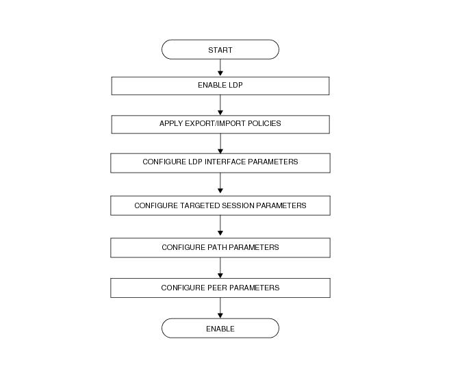
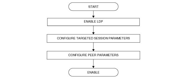
Step 3
After the user has detected that at least, one link LDP or T-LDP adjacency has been brought down by the resource exhaustion mechanism, he/she must protect the router by applying one or more of the following to free resources up:
Step 4
Next, the user has to manually attempt to clear the overload (no resource) state and allow the router to attempt to restore the link and targeted sessions to its peer.
Please note that due to the dynamic nature of FEC distribution and resolution by LSR nodes, one cannot predict exactly which FECs and which interfaces or targeted peers will be restored after performing the following commands if the LSR activates resource exhaustion again.
One of the following commands can be used:
- [clear router ldp resource-failures]
- [clear router ldp interface ifName ]
- [clear router ldp peer peerAddress]
These 2 commands *DO NOT* Clear the overload state for the local FECs.
 
Enhanced Resource Handling Procedures
Step 1
If the peer AND the local LSR do support the Overload Protection Capability it means that the LSR will signal the overload state for the FEC type which caused the resource exhaustion as part of the enhanced resource handling mechanism.
In order to verify if the local router has received or sent the overload status TLV, perform the following:
-	[show router ldp session detail]
show router ldp session 110.20.1.1 detail
-------------------------------------------------------------------------------
Session with Peer 110.20.1.1:0, Local 110.20.1.110:0
-------------------------------------------------------------------------------
Adjacency Type : Both State : Established
Up Time : 0d 00:05:48
Max PDU Length : 4096 KA/Hold Time Remaining : 24
Link Adjacencies : 1 Targeted Adjacencies : 1
Local Address : 110.20.1.110 Peer Address : 110.20.1.1
Local TCP Port : 51063 Peer TCP Port : 646
Local KA Timeout : 30 Peer KA Timeout : 45
Mesg Sent : 442 Mesg Recv : 2984
FECs Sent : 16 FECs Recv : 2559
Addrs Sent : 17 Addrs Recv : 1054
GR State : Capable Label Distribution : DU
Nbr Liveness Time : 0 Max Recovery Time : 0
Number of Restart : 0 Last Restart Time : Never
P2MP : Capable MP MBB : Capable
Dynamic Capability : Not Capable LSR Overload : Capable
Advertise : Address/Servi* BFD Operational Status : inService
Addr FEC OverLoad Sent : Yes Addr FEC OverLoad Recv : No <---- // this LSR sent overLoad for unicast FEC type to peer
Mcast FEC Overload Sent: No Mcast FEC Overload Recv: No
Serv FEC Overload Sent : No Serv FEC Overload Recv : No
-------------------------------------------------------------------------------
 
show router ldp session 110.20.1.110 detail
-------------------------------------------------------------------------------
Session with Peer 110.20.1.110:0, Local 110.20.1.1:0
-------------------------------------------------------------------------------
Adjacency Type : Both State : Established
Up Time : 0d 00:08:23
Max PDU Length : 4096 KA/Hold Time Remaining : 21
Link Adjacencies : 1 Targeted Adjacencies : 1
Local Address : 110.20.1.1 Peer Address : 110.20.1.110
Local TCP Port : 646 Peer TCP Port : 51063
Local KA Timeout : 45 Peer KA Timeout : 30
Mesg Sent : 3020 Mesg Recv : 480
FECs Sent : 2867 FECs Recv : 16
Addrs Sent : 1054 Addrs Recv : 17
GR State : Capable Label Distribution : DU
Nbr Liveness Time : 0 Max Recovery Time : 0
Number of Restart : 0 Last Restart Time : Never
P2MP : Capable MP MBB : Capable
Dynamic Capability : Not Capable LSR Overload : Capable
Advertise : Address/Servi* BFD Operational Status : inService
Addr FEC OverLoad Sent : No Addr FEC OverLoad Recv : Yes <---- // this LSR received overLoad for unicast FEC type from peer
Mcast FEC Overload Sent: No Mcast FEC Overload Recv: No
Serv FEC Overload Sent : No Serv FEC Overload Recv : No
===============================================================================
A trap is also generated:
70002 2013/07/17 16:06:59.46 PST MINOR: LDP #2008 Base LDP Session State Change 		"Session state is operational. Overload Notification message is sent to/from peer   110.20.1.1:0 with overload state true for fec type prefixes"
Step 2
Besides interfaces and targeted peer, locally originated FECs may also be put into overload. These are the following:
- unicast fec-originate pop
- multicast local static p2mp-fec type=1 [on leaf LSR]
- multicast local Dynamic p2mp-fec type=3 [on leaf LSR]
The user can check if only remote and/or local FECs have been set in overload by the resource enhanced resource exhaustion mechanism using the following command:
- [tools dump router ldp instance]
The relevant part of the output is described below:
	  Num Entities OLoad (FEC: Address Prefix  ):  Sent: 7           Rcvd: 0   <----- // # of session in OvLd for fec-type=unicast
Num Entities OLoad (FEC: PWE3 ): Sent: 0 Rcvd: 0 <----- // # of session in OvLd for fec-type=service
Num Entities OLoad (FEC: GENPWE3 ): Sent: 0 Rcvd: 0 <----- // # of session in OvLd for fec-type=service
Num Entities OLoad (FEC: P2MP ): Sent: 0 Rcvd: 0 <----- // # of session in OvLd for fec-type=MulticastP2mp
Num Entities OLoad (FEC: MP2MP UP ): Sent: 0 Rcvd: 0 <----- // # of session in OvLd for fec-type=MulticastMP2mp
Num Entities OLoad (FEC: MP2MP DOWN ): Sent: 0 Rcvd: 0 <----- // # of session in OvLd for fec-type=MulticastMP2mp
Num Active Adjacencies: 9
Num Interfaces: 6 Num Active Interfaces: 6
Num OLoad Interfaces: 0 <----- // link LDP interfaces in resource exhaustion should be zero when Overload Protection Capability is supported
Num Targ Sessions: 72 Num Active Targ Sess: 67
Num OLoad Targ Sessions: 0 <----- // T-LDP peers in resource exhaustion should be zero if Overload Protection Capability is supported
Num Addr FECs Rcvd: 8667 Num Addr FECs Sent: 91
Num Addr Fecs OLoad: 1 <----- // # of local/remote unicast Fecs in Overload
Num Svc FECs Rcvd: 3111 Num Svc FECs Sent: 0
Num Svc FECs OLoad: 0 <----- // # of local/remote service Fecs in Overload
Num mcast FECs Rcvd: 0 Num Mcast FECs Sent: 0
Num mcast FECs OLoad: 0 <----- // # of local/remote multicast Fecs in Overload
Num MAC Flush Rcvd: 0 Num MAC Flush Sent: 0
When at least one local FEC has been set in overload the following trap will occur:
69999 2013/07/17 16:06:59.21 PST MINOR: LDP #2002 Base LDP Resources Exhausted "Instance state changed - vRtrID: 1, administrative state: inService, operational state: inService"
Step 3
After the user has detected that at least one overload status TLV has been sent or received by the LSR, he/she must protect the router by applying one or more of the following to free resources up:
Step 4
Next, the user has to manually attempt to clear the overload state on the affected sessions and for the affected FEC types and allow the router to clear the overload status TLV to its peers.
Please note that due to the dynamic nature of FEC distribution and resolution by LSR nodes, one cannot predict exactly which sessions and which FECs will be cleared after performing the following commands if the LSR activates overload again.
One of the following commands can be used depending if the user wants to clear all sessions or at once or one session at a time:
- [clear router ldp resource-failures]
- [clear router ldp session a.b.c.d overload fec-type {services|prefixes|multicast}]
 
LDP Process Overview
Figure 46 displays the process to provision basic LDP parameters.
Figure 46: LDP Configuration and Implementation