For feedback and comments:
documentation.feedback@alcatel-lucent.com

Table of Contents Previous Next PDF


GMPLS
In This Chapter
This chapter provides information to configure GMPLS.
GMPLS
The Generalized Multi-Protocol Label Switching (GMPLS) User to Network Interface (UNI) permits dynamic provisioning of optical transport connections between IP routers and optical network elements in order to reduce the operational time and administrative overhead required to provision new connectivity. The optical transport connections typically originate and terminate in an IP/MPLS controlled domain and traverse an intermediate optical transport network. The GMPLS UNI model is based on an overlay approach, whereby the IP/MPLS control plane is transported transparently over the intermediate transport network, which itself is controlled by a GMPLS control plane.
The UNI provides a clear demarcation point between the domains of responsibility of the parties involved in managing the overlying IP/MPLS network and the underlying optical network. For example, these parties could be two divisions in a service provider organization, or a subscriber/client of the service provider and the service provider itself.
The UNI has a client part, the UNI-C, and a network part, the UNI-N. In the Alcatel-Lucent solution, the UNI-C is an SR OS system, such as a 7750 SR or a 7950 XRS, while the UNI-N is an optical device; for example, an 1830 PSS.
Control plane related information is exchanged between the UNI-C and the UNI-N using a dedicated out of band communication channel. Note that the adjacent optical network element and the router assume that they are connected to a trusted peer, and thus assume a secure communication. This is achieved by physically securing the link carrying the control channel between the two.
Based on standardized UNI messaging (RFC 4208), the UNI-C indicates to the UNI-N which far-end peer UNI-C node (corresponding to a remote router) to make an optical transport connection to. This path request can include additional path attributes to indicate requirements such as bandwidth, priority and diversity/resiliency parameters.
 
Example Applications
This section summarizes some of the use cases that the GMPLS UNI may be used to address.
Use Case 1: Dynamic Connection Setup with Constraints
This use case aims to solve inefficiencies between IP and transport teams within an operator for connectivity setup; for example:
It therefore aims to optimize IP/Optical transport team interactions by removing complex processes, and reduces per-connection provisioning in the optical core.
The UNI should allow the setup/maintenance/release of connections across an intermediate optical transport network from a UNI-C router to another remote UNI-C router. The routers are connected to an optical network that consists of optical cross connects (OXCs), and the interconnection between the OXC and the router is based on the GMPLS UNI (RFC 4208). The UNI-C routers are 7x50 nodes, while the UNI-N OXC is the 1830 PSS. The UNI connection is instantiated using a GMPLS LSP (gLSP).
The 7x50 UNI-C is always the initiator of the connection. The only per-connection configuration occurs at the UNI-C, and it is operator initiated. Connections to any of the remote UNI-C routers are signaled over the UNI. The initiation of a connection request is via CLI or SNMP to the UNI-C router.
Signaling is based on RSVP-TE (RFC 4208). Constraints can be signaled with a connection setup request. These include bandwidth, protection type, and latency. In the event that a connection could not be established, a correct (descriptive) error code is returned to the initiator.
Figure 36: Dynamic Connection Setup
 
Use Case 2: Multi-Layer Resiliency
The objective of this application is to ensure optical network path diversity for primary/backup paths of an overlay IP network. It thus aims to resolve situations where the UNI-C router has no topological visibility of the optical network, and to allow the router to indicate that paths have to be either co-routed or avoid specific optical nodes or links along a path.
Route diversity for LSPs from single homed UNI-C router and dual-homed UNI-C router is a common requirement in optical transport networks. Dual homing is typically used to avoid a single point of failure (for example, the UNI link or OXC) or to allow two disjoint connections to form a protection group.
For the dual-homing case, it is possible to establish two connections from the source router to the same destination router where one connection is using one UNI link to, for example, OXC1 and the other connection is using the UNI link to OXC2. In order to avoid single points of failure within the optical network, it is necessary to also ensure path (gLSP) diversity within the provider network in order to achieve end-to-end diversity for the two gLSPs between the two routers.
Figure 37: Multi-Layer Resiliency
As the two connections are entering the provider network at different OXC devices, the OXC device that receives the connection request for the second connection needs to be capable of determining the additional path computation constraints such that the path of the second LSP is disjointed with respect to the already established first connection entering the network at a different PE device.
 
GMPLS UNI Architecture
This section specifies the architectural and functional elements of the GMPLS UNI on the 7x50 and 1830 (which must be GMRE), and how they relate to one another. The architecture is illustrated in Figure 38.
Figure 38: GMPLS UNI Architecture
On the UNI-C side, the UNI consists of the following functional components:
Although the architecture figure shows a single 7x50 connected to a single UNI-N (1830 PSS), it is possible to multi-home a 7x50 into more than one (usually two) UNI-Ns at the edge of the optical network. In this case, a separate IPCC, set of data bearers, and set of TE links, is required between the 7x50 and each UNI-N.
 
Addressing and End-to-End gLSP Architecture
The GMPLS UNI assumed a flat addressing scheme between the UNI-C nodes and the optical network. In this model, a common addressing scheme is used between the UNI-C (IP router) and UNI-N (optical edge). The UNI-C and UNI-N must be in the same subnet. Also, none of the UNI-C addresses can overlap or clash with any of the GMPLS-aware nodes in the optical network. This does not mandate that the whole IP network share a common address space with the optical network, as a separate loopback address can be used for the GMPLS UNI on the UNI-C.
The ERO Expansion (RFC 5151) model is assumed for the GMPLS LSPs. The UNI-C is not exposed to the full ERO between the UNI-N nodes. Instead, the full ERO is inserted at the UNI-N. This model limits the sharing of topology information between the UNI-N and UNI-C.
1830 PSS Identifiers
This section describes the various identifiers used on the 1830 PSS that are relevant to configuring the GMPLS UNI on the 7x50 in conjunction with the 1830 PSS. The following figure illustrates the identifier architecture of an 1830 PSS multi-shelf system. The multi-shelf system consists of a control plane node and one or more data plane nodes. The following identifiers are used:
Figure 39: Identifier Architecture
Recovery Reference Models
This section details the supported recovery reference models. These models are based on the mechanisms specified in RFC 4872 and RFC 4873.
The following figure presents a generalized reference model in which the 7x50 UNI-C nodes are dual-homed at the link layer to the 1830 PSS UNI-N nodes. Not all elements of this architecture may be required in all deployment cases.
Figure 40: General GMPLS UNI Interconnection Architecture
This reference model includes two 7x50 nodes, each hosting a UNI-C function, at the edge of each IP network facing two 1830 PSS nodes, each hosting a UNI-N function. A full mesh of black and while Ethernet links interconnects neighboring UNI-C nodes and UNI-N nodes. Parallel links may exist, so that a given 7x50 UNI-C is connected to a neighbor 1830 PSS UNI-N by more then one Ethernet link.
Each 7x50 hosting a UNI-C has an IPCC to each of the two 1830 PSS UNI-Ns. Likewise, each 1830 PSS hosting UNI-N has an IPCC to both of the 7x50 UNI-Cs that it is connected to. IPCCs only exist between UNI-C and UNI-N nodes, and not between UNI-C nodes. A control plane (LMP and RSVP) adjacency therefore exists between each UNI-C and it's corresponding UNI-Ns.
Recovery in the following domains is supported in the following locations:
The following subsections detail some example recovery options that are possible using either GMPLS, or a combination of GMPLS mechanisms and mechanisms in the overlay IP network. Note that some of the functionality shown in one of the scenarios can be used in combination with functionality in another scenario, for example optical SRLG diversity.
The objective of GMPLS here is to minimize the disruption to the overlay IP network while simultaneously maximizing the utilization of both the gLSPs and the resources in the underlying optical network (or UNI links).
 
End to End Recovery (IP-layer)
End to end recovery applies to protection against failures at any point along the entire path between a local UNI-C and a far end UNI-C. In the context of the GMPLS UNI, recovery can be implemented in the overlay IP network either at Layer 3 or Layer 2, with assistance from the underlay optical network, with optional additional protection and/or restoration of gLSPs by GMPLS.
 
End to End ECMP
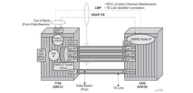
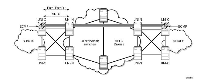
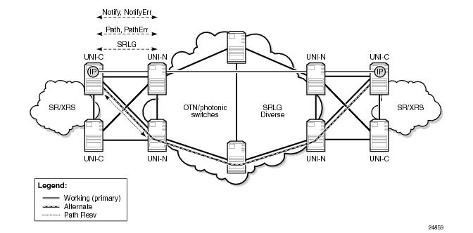
Figure 41 illustrates the first model. Multiple gLSPs are established between a pair of remote UNI-C nodes. Each gLSP is bound to a separate IP network interface at the UNI-C. RSVP signaling across the UNI is used to ensure that the gLSPs are SRLG diverse (by explicitly signaling the SRLG list to avoid in an XRO for every gLSP, or automatically collecting the SRLG list for a gLSP which does not have an XRO, and then signaling a subsequent gLSP including this collected list in its XRO). Protection is provided at the IP layer by hashing across the IP network interfaces associated with each gLSP. The operational state of each IP interface can be tied to the operational state of its gLSP (controlled using RSVP) or using mechanisms in the IP overlay such as BFD.
Figure 41: End-to-End ECMP with gLSP Diversity Across Single UNI-C
 
End to End Load Sharing Using a Load Sharing GMPLS Tunnel Group
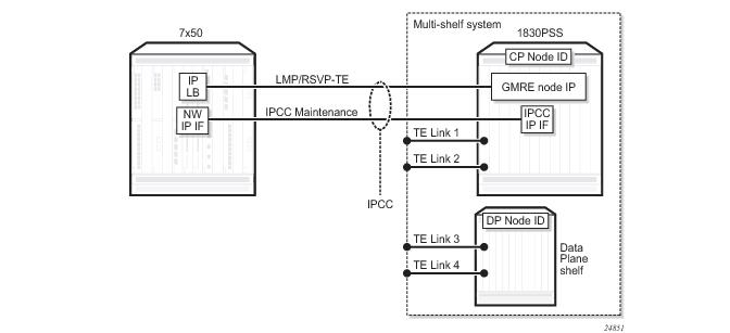
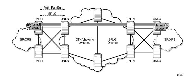
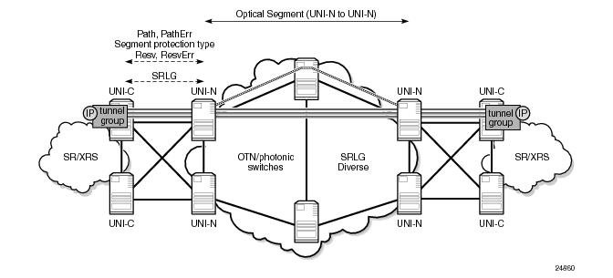
Figure 42 shows the case where multiple gLSPs, instantiated as black and white Ethernet ports, are bundled together in a similar manner to LAG, using a GMPLS tunnel group. That is, each member gLSP of a tunnel group effectively maps to a member port, which runs end to end between remote UNI-Cs. Note that a LAG does not and cannot terminate on the neighboring 1830 PSS UNI-N. A single IP network interface is bound to the bundle of ports represented by the gLSPs. LACP does not run across the bundle; RSVP signaling is instead used to convey the state of the gLSP and thus the corresponding member port of the tunnel group. Traffic is load shared across the tunnel group members.
Figure 42: End-to-End Load Sharing GMPLS Tunnel Group with gLSP Path Diversity
 
End to End Recovery (GMPLS Layer)
 
Unprotected gLSP
The default level of E2E recovery is unprotected. In this case, a gLSP can only recover from a failure when the downstream resource that failed is recovered. The following figure illustrates this. When a gLSP fails in the optical network, a failure notification is propagated to the source UNI-C node e.g. using a PathErr or a NotifyErr LSP Failure message. The source UNI-C node takes no action, but will continue to refresh the PATH message for this gLSP, which may be rerouted around the failure by the optical network e.g. if the IGP in the optical network reconverges. The gLSP is treated as operationally down until a message indicating that the gLSP has been restored is received by the 7x50; for example, a Notify Error LSP Restored.
Figure 43: gLSP Re-Establishment (PATH Refresh)
 
Full LSP Rerouting
Full LSP rerouting (or restoration), specified in RFC 4872 section 11, switches normal traffic to an alternate LSP that is not even partially established until after the working LSP failure occurs. The new alternate route is selected at the LSP head-end node; it may reuse resources of the failed LSP at intermediate nodes and may include additional intermediate nodes and/or links.
Figure 44: Full LSP Rerouting
 
1: N Protection
In 1:N (N >= 1) protection, the protecting LSP path is a fully provisioned and resource-disjoint LSP path from the N working LSP paths. The N working LSP paths may also be mutually resource-disjoint. Coordination between end-nodes is required when switching from one of the working paths to the protecting path. Note that although RFC4872 allows extra traffic on the protecting path, this is not supported by the 7x50. Figure 45 illustrates this protection architecture when N=1, while Figure 46 shows the case for N>1.
Figure 45: 1:N Protection, with N=1 (RFC4872)
Figure 46: N>1 Protection
 
Optical Segment Recovery
Optical segment protection refers to the ability of the optical network to protect the span of a gLSP between ingress and egress UNI-N nodes. It does not require any protection switching on the UNI-C nodes. However, it does require the UNI-C to signal a request for a particular segment protection type towards the UNI-N in the PATH message for a gLSP. The optical network may either accept this request, reject it or respond with an alternative. Segment protection is defined in RFC 4873.
Figure 47: Optical Segment Protection Domain
Signaling of the following segment protection types is supported by the 7x50: