For feedback, use the following:
ipd_online_feedback@alcatel-lucent.com
Table of Contents Previous Next Index PDF


Services Overview
In This Section
This section provides an overview of the 7750 SR-Series subscriber services, service model and service entities. Additional details on the individual subscriber services can be found in subsequent chapters.
Topics in this section include:
Introduction
A service is a globally unique entity that refers to a type of connectivity service for either Internet or VPN connectivity. Each service is uniquely identified by a service ID and an optional service name within a service area. The SR-Series service model uses logical service entities to construct a service. In the service model, logical service entities provide a uniform, service-centric configuration, management, and billing model for service provisioning.
In the SR-Series services can provide Layer 2/bridged service or Layer 3/IP routed connectivity between a service access point (SAP) on one router and another service access point (a SAP is where traffic enters and exits the service) on the same (local) router or another router (distributed). A distributed service spans more than one router.
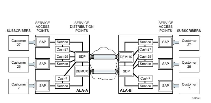
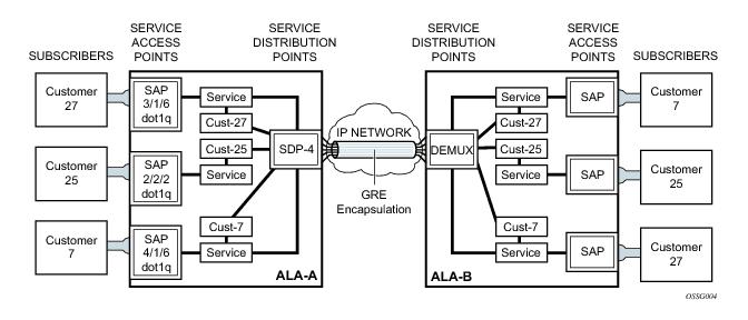
Distributed services use service distribution points (SDPs) to direct traffic to another SR-Series through a service tunnel. SDPs are created on each participating router, specifying the origination address (the router participating in the service communication) and the destination address of another router. SDPs are then bound to a specific customer service. Without the binding process, far-end router is not able to participate in the service (there is no service without associating an SDP with a service).
 
Service Types
The SR-Series offers the following types of subscriber services which are described in more detail in the referenced chapters:
IP Pipe (Ipipe) — Provides IP connectivity between a host attached to a point-to-point access circuit (FR, ATM, PPP) with routed IPv4 encapsulation and a host attached to an Ethernet interface. See IP Interworking VLL (Ipipe) Services.
Virtual Private LAN Service (VPLS) — A Layer 2 multipoint-to-multipoint VPN. See Virtual Private LAN Service. VPLS includes Hierarchical VPLS (H-VPLS) which is an enhancement of VPLS which extends Martini-style signaled or static virtual circuit labeling outside the fully meshed VPLS core.
Internet Enhanced Service (IES) — A direct Internet access service where the customer is assigned an IP interface for Internet connectivity. See Internet Enhanced Service.
Circuit Emulation Service (Cpipe) — Circuits encapsulated in MPLS use circuit pipes (Cpipes) to connect to the far end circuit. Cpipes support either SAP-spoke SDP or SAP-SAP connections.
 
Service Policies
Common to all SR-Series connectivity services are policies that are assigned to the service. Policies are defined at a global level and then applied to a service on the router. Policies are used to define SR-Series service enhancements. The types of policies that are common to all SR-Series connectivity services are:
QoS ingress and egress policies determine the QoS characteristics for a SAP. A QoS policy applied to a SAP specifies the number of queues, queue characteristics (such as forwarding class, committed, and peak information rates, etc.) and the mapping of traffic to a forwarding class. A QoS policy must be created before it can be applied to a SAP. A single ingress and a single egress QoS policy can be associated with a SAP.
Filter policies, also referred to as access control lists (ACLs), control the traffic allowed in or out of a SAP based on MAC or IP match criteria. Associating a filter policy on a SAP is optional. Filter policies are identified by a unique filter policy ID. A filter policy must be created before it can be applied to a SAP. A single ingress and single egress filter policy can be associated with a SAP.
The routers provide a comprehensive set of service-related counters. Accounting data can be collected on a per-service, per-forwarding class basis, which enables network operators to accurately measure network usage and bill each customer for each individual service using any of a number of different billing models.
 
Multipoint Shared Queuing
Multipoint shared queuing is supported to minimize the number of multipoint queues created for ingress VPLS, IES or VPRN SAPs or ingress subscriber SLA profiles. Normally, ingress multipoint packets are handled by multipoint queues created for each SAP or subscriber SLA profile instance. In some instances, the number of SAPs or SLA profile instances are sufficient for the in use multipoint queues to represent many thousands of queues on an ingress forwarding plane. If multipoint shared queuing is enabled for the SAPs or SLA profile instances on the forwarding plane, the multipoint queues are not created. Instead, the ingress multipoint packets are handled by the unicast queue mapped to the forwarding class of the multipoint packet.
Functionally, multipoint shared queuing is a superset of shared queuing. With shared queuing on a SAP or SLA profile instance, only unicast packets are processed twice, once for the initial service level queuing and a second time for switch fabric destination queuing. Shared queuing does not affect multipoint packet handling. Multipoint packet handling in normal (service queuing) is the same as shared queuing. When multipoint shared queuing is enabled, shared queuing for unicast packets is automatically enabled.
 
Ingress Queuing Modes of Operation
Three modes of ingress SAP queuing are supported for multipoint services (IES, VPLS and VPRN); service, shared, and multipoint shared. The same ingress queuing options are available for IES and VPLS subscriber SLA profile instance queuing.
 
Ingress Service Queuing
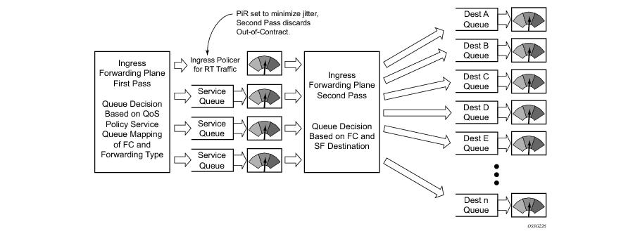
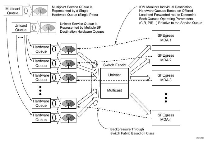
Normal or service queuing is the default mode of operation for SAP ingress queuing. Service queuing preserves ingress forwarding bandwidth by allowing a service queue defined in an ingress SAP QoS policy to be represented by a group of hardware queues. A hardware queue is created for each switch fabric destination to which the logical service queue must forward packets. For a VPLS SAP with two ingress unicast service queues, two hardware queues are used for each destination forwarding engine the VPLS SAP is forwarding to. If three switch fabric destinations are involved, six queues are allocated (two unicast service queues multiplied by three destination forwarding complexes equals six hardware queues). Figure 1 demonstrates unicast hardware queue expansion. Service multipoint queues in the ingress SAP QoS policy are not expanded to multiple hardware queues, each service multipoint queue defined on the SAP equates to a single hardware queue to the switch fabric.
When multiple hardware queues represent a single logical service queue, the system automatically monitors the offered load and forwarding rate of each hardware queue. Based on the monitored state of each hardware queue, the system imposes an individual CIR and PIR rate for each queue that provides an overall aggregate CIR and PIR reflective of what is provisioned on the service queue.
Figure 1: Unicast Service Queue Mapping to Multiple Destination Based Hardware Queues
 
Ingress Shared Queuing
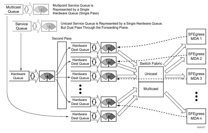
To avoid the hardware queue expansion issues associated with normal service based queuing, the system allows an ingress logical service queue to map to a single hardware queue when shared queuing is enabled. Shared queuing uses two passes through the ingress forwarding plane to separate ingress per service queuing from the destination switch fabric queuing. In the case of shared queuing, ingress unicast service queues are created one-for-one relative to hardware queues. Each hardware queue representing a service queue is mapped to a special destination in the traffic manager that ‘forwards’ the packet back to the ingress forwarding plane allowing a second pass through the traffic manager. In the second pass, the packet is placed into a ‘shared’ queue for the destination forwarding plane. The shared queues are used by all services configured for shared queuing.
When the first SAP or SLA profile instance is configured for shared queuing on an ingress forwarding plane, the system allocates eight hardware queues per available destination forwarding plane, one queue per forwarding class. (Twenty four hardware queues are also allocated for multipoint shared traffic, but that is discussed in the following section.) The shared queue parameters that define the relative operation of the forwarding class queues are derived from the Shared Queue policy defined in the QoS CLI node. Figure 2 demonstrates shared unicast queuing. SAP or SLA profile instance multipoint queuing is not affected by enabling shared queuing. Multipoint queues are still created as defined in the ingress SAP QoS policy and ingress multipoint packets only traverse the ingress forwarding plane a single time.
Enabling shared queuing may affect ingress performance due to double packet processing through the service and shared queues.
Figure 2: Unicast Service Queuing With Shared Queuing Enabled
Figure 3: Multipoint Queue Behavior with Shared Queuing Enabled
 
Ingress Multipoint Shared Queuing
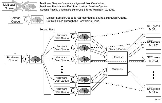
Ingress multipoint shared queuing is a variation to the unicast shared queuing defined in Ingress Shared Queuing. Ingress unicast service queues are mapped one-for-one with hardware queues and unicast packets traverse the ingress forwarding plane twice. In addition to the above, the multipoint queues defined in the ingress SAP QoS policy are not created. Instead, multipoint packets (broadcast, multicast and unknown unicast destined) are treated to the same dual pass ingress forwarding plane processing as unicast packets. In the first pass, the forwarding plane uses the unicast queue mappings for each forwarding plane. The second pass uses the multipoint shared queues to forward the packet to the switch fabric for special replication to all egress forwarding planes that need to process the packet.
The benefit of defining multipoint shared queuing is the savings of the multipoint queues per service. By using the unicast queues in the first pass and then the aggregate shared queues in the second pass, per service multipoint queues are not required. The predominate scenario where multipoint shared queuing may be required is with subscriber managed QoS environments using a subscriber per SAP model. Usually, ingress multipoint traffic is minimal per subscriber and the extra multipoint queues for each subscriber reduces the overall subscriber density on the ingress forwarding plane. Multipoint shared queuing eliminates the multipoint queues sparing hardware queues for better subscriber density. Figure 4 demonstrates multipoint shared queuing.
One disadvantage of enabling multipoint shared queuing is that multipoint packets are no longer managed per service (although the unicast forwarding queues may provide limited benefit in this area). Multipoint packets in a multipoint service (VPLS, IES and VPRN) use significant resources in the system, consuming ingress forwarding plane multicast bandwidth and egress replication bandwidth. Usually, the per service unicast forwarding queues are not rate limited to a degree that allows adequate management of multipoint packets traversing them when multipoint shared queuing is enabled. It is possible to minimize the amount of aggregate multipoint bandwidth by setting restrictions on the multipoint queue parameters in the QoS node’s shared queue policy. Aggregate multipoint traffic can be managed per forwarding class for each of the three forwarding types (broadcast, multicast or unknown unicast – broadcast and unknown unicast are only used by VPLS).
A second disadvantage to multipoint shared queuing is the fact that multipoint traffic now consumes double the ingress forwarding plane bandwidth due to dual pass ingress processing.
Figure 4: Multipoint Shared Queuing Using First Pass Unicast Queues
­Alcatel-Lucent Service Model
In the ­Alcatel-Lucent service model, the service edge routers are deployed at the provider edge. Services are provisioned on the service routers and transported across an IP and/or IP/MPLS provider core network in encapsulation tunnels created using generic router encapsulation (GRE) or MPLS label switched paths (LSPs).
The service model uses logical service entities to construct a service. The logical service entities are designed to provide a uniform, service-centric configuration, management, and billing model for service provisioning. Some benefits of this service-centric design include:
Changes are made to a single logical entity rather than multiple ports on multiple devices. It is easier to change one tunnel rather than several services.
The operational integrity of a logical entity (such as a service tunnel and service end points) can be verified rather than dozens of individual services improving management scaling and performance.
Service provisioning uses logical entities to provision a service where additional properties can be configured for bandwidth provisioning, QoS, security filtering, accounting/billing to the appropriate entity.
 
Service Entities
The basic logical entities in the service model used to construct a service are:
Customers (see )
Service Distribution Points (SDPs) (see ) (for distributed services only)
Figure 5: Service Entities
 
Customers
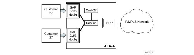
The terms customers and subscribers are used synonymously. The most basic required entity is the customer ID value which is assigned when the customer account is created. To provision a service, a customer ID must be associated with the service at the time of service creation.
 
Service Access Points (SAPs)
Each subscriber service type is configured with at least one service access point (SAP). A SAP identifies the customer interface point for a service on an ­Alcatel-Lucent router (Figure 6). The SAP configuration requires that slot, XMA/MDA, and port/channel information be specified. The slot, XMA/MDA, and port/channel parameters must be configured prior to provisioning a service (see the Cards, MDAs, and Ports sections of the OS Interface Guide).
A SAP is a local entity to the router and is uniquely identified by:
The physical Ethernet port or SONET/SDH port or TDM channel
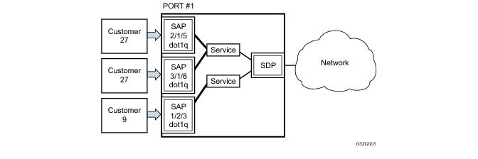
Depending on the encapsulation, a physical port or channel can have more than one SAP associated with it. SAPs can only be created on ports or channels designated as “access” in the physical port configuration. SAPs cannot be created on ports designated as core-facing “network” ports as these ports have a different set of features enabled in software.
Figure 6: Service Access Point (SAP)
A SAP can also be associated with a PW Port rather than an access port. Such SAPs are called PW SAPs. It is only applicable to IES or VPRN services. PW Ports represent pseudowires in enhanced subscriber management (ESM). For a description of PW Ports, see the SR OS Triple Play Guide.
 
SAP Encapsulation Types and Identifiers
The encapsulation type is an access property of a service Ethernet port or SONET/SDH or TDM channel. The appropriate encapsulation type for the port or channel depends on the requirements to support multiple services on a single port/channel on the associated SAP and the capabilities of the downstream equipment connected to the port/channel. For example, a port can be tagged with IEEE 802.1Q (referred to as dot1q) encapsulation in which each individual tag can be identified with a service. A SAP is created on a given port or channel by identifying the service with a specific encapsulation ID.
 
Ethernet Encapsulations
The following lists encapsulation service options on Ethernet ports:
Dot1q — Supports multiple services for one customer or services for multiple customers (Figure 7). For example, the port is connected to a multi-tenant unit (MTU) device with multiple downstream customers. The encapsulation ID used to distinguish an individual service is the VLAN ID in the IEEE 802.1Q header.
There are several encapsulation service options on SONET/SDH channels:
Internet Protocol Control Protocol (IPCP) — Supports a single IP service on a SONET/SDH port or a single service per channel (if the interface is channelized). This is typically used for router interconnection using point-to-point protocol (PPP).
Bridging Control Protocol (BCP-null) — Supports a single service on the SONET/SDH port or a single service per channel (if the interface is channelized). This is used for bridging a single service between two devices using PPP over SONET/SDH. The encapsulation ID is always 0 (zero).
Bridging Control Protocol (BCP-dot1q) — Supports multiple services on the SONET/SDH port/channel. This encapsulation type is used for bridging multiple services between two devices using PPP over SONET/SDH. The encapsulation ID used to distinguish services is the VLAN ID in the IEEE 802.1Q header in the BCP-encapsulated frame.
Figure 7: Multiple SAPs on a Single Port/Channel
 
Default SAP on a Dot1q Port
This feature introduces default SAP functionality on Dot1q-encapsulated ports. This is similar to the functionality provided by Q1* SAP on QinQ encapsulated ports, meaning that on On dot1q-encapsulated ports where a default SAP is configured, all packets with q-tags not matching any explicitly defined SAPs will be assigned to this SAP. SAPs with default QinQ encapsulation are supported in VPLS, Epipe, IES and VPRN services. Both DHCP snooping and IGMP snooping are supported for QinQ SAPs. In this context, the character “*” indicates default which means allow through. A 0 value means that it should not be there which allows the Qtag to be missing.
One of the applications where this feature can be applicable is an access connection of a customer who uses the whole port to access Layer 2 services. The internal VLAN tags are transparent to the service provider. This can be provided by a null encapsulated port. A dedicated VLAN (not used by the user) can be used to provide CPE management.
In this type of environment, logically two SAPs exist, a management SAP and a service SAP. The management SAP can be created by specifying a VLAN tag which is reserved to manage the CPE. The service SAP covers all other VLANs and behaves as a SAP on a null-encapsulated port.
There a few constraints related for the use of default SAP on a Dot1q-encapsulated port:
This type of SAP is supported only on VPLS and Epipe services and cannot be created in IES and VPRN services as it cannot preserve VLAN tag markings.
This type of SAP is mutually exclusive with a SAP defined by explicit null encapsulation (for example, 1/1/1:0). This avoids conflict as to which SAP untagged frames should be associated.
 
Services and SAP Encapsulations
:
 
SAP Configuration Considerations
When configuring a SAP, consider the following:
There are no default SAPs. All SAPs in subscriber services must be created.
When a SAP is deleted, all configuration parameters for the SAP will also be deleted. For Internet Enhanced Service (IES), the IP interface must be shutdown before the SAP on that interface may be removed.
A port/channel with a dot1q or BCP-dot1q encapsulation type means the traffic for the SAP is identified based on a specific IEEE 802.1Q VLAN ID value. The VLAN ID is stripped off at SAP ingress and the appropriate VLAN ID placed on at SAP egress. As a result, VLAN IDs only have local significance, so the VLAN IDs for the SAPs for a service need not be the same at each SAP.
If a port/channel is administratively shutdown, all SAPs on that port/channel will be operationally out of service.
 
G.8032 Protected Ethernet Rings
Ethernet ring protection switching offers ITU-T G.8032 specification compliance to achieve resiliency for Ethernet Layer 2 networks. G.8032 (Ethernet-ring) is built on Ethernet OAM and often referred to as Ring Automatic Protection Switching (R-APS).
For further information on Ethernet rings, see G.8032 Ethernet Ring Protection Switching.
 
 
Service Distribution Points (SDPs)
A service distribution point (SDP) acts as a logical way to direct traffic from one router to another through a uni-directional (one-way) service tunnel. The SDP terminates at the far-end device which directs packets to the correct service egress SAPs on that device. A distributed service consists of a configuration with at least one SAP on a local node, one SAP on a remote node, and an SDP binding the service to the service tunnel.
An SDP has the following characteristics:
An SDP from the local device to a far-end router requires a return path SDP from the far-end SR-SeriesESS-Series back to the local router. Each device must have an SDP defined for every remote router to which it wants to provide service. SDPs must be created first, before a distributed service can be configured.
 
SDP Binding
To configure a distributed service from ALA-A to ALA-B, the SDP ID (1) (shown in Figure 8) must be specified in the service creation process in order to “bind” the service to the tunnel (the SDP). Otherwise, service traffic is not directed to a far-end point and the far-end device(s) cannot participate in the service (there is no service). To configure a distributed service from ALA-B to ALA-A, the SDP ID (5) must be specified.
 
Figure 8: GRE Service Distribution Point (SDP) Pointing from ALA-A to ALA-B
 
Spoke and Mesh SDPs
When an SDP is bound to a service, it is bound as either a spoke SDP or a mesh SDP. The type of SDP indicates how flooded traffic is transmitted.
A spoke SDP is treated like the equivalent of a traditional bridge “port” where flooded traffic received on the spoke SDP is replicated on all other “ports” (other spoke and mesh SDPs or SAPs) and not transmitted on the port it was received.
All mesh SDPs bound to a service are logically treated like a single bridge “port” for flooded traffic where flooded traffic received on any mesh SDP on the service is replicated to other “ports” (spoke SDPs and SAPs) and not transmitted on any mesh SDPs.
 
SDP Using BGP Route Tunnel
SDP is enhanced to use BGP route tunnel to extend inter-AS support for L2VPN services. An SDP can be configured based on service transport method (for example, GRE or MPLS tunnel). MPLS SDP support is enhanced to allow a BGP route tunnel to reach the far-end PE.
A single method of tunneling is allowed per SDP (for example, LDP, RSVP-TE LSP or BGP route tunnel). BGP route tunnel method is excluded if multi-mode transport is enabled for an SDP.
For the inter-AS far-end PE, next-hop for BGP route tunnel must be one of the local ASBR. The LSP type selected to reach the local ASBR (BGP labeled route next-hop) must be configured under the BGP global context. LDP must be supported to provide transport LSP to reach the BGP route tunnel next-hop.
Only BGP route labels can be used to transition from ASBR to the next-hop ASBR. The global BGP route tunnel transport configuration option must be entered to select an LSP to reach the PE node from ASBR node. On the last BGP segment, both “BGP+LDP” and LDP routes may be available to reach the far-end PE from the ASBR node. LDP LSP must be preferred due to higher protocol priority. This leads to just one label besides other labels in stack to identify VC/VPN at far-end PE nodes.
 
SDP Keepalives
SDP keepalives actively monitor the SDP operational state using periodic ­Alcatel-Lucent SDP ping echo request and echo reply messages. ­Alcatel-Lucent SDP ping is a part of Alcatel-Lucent’s suite of service diagnostics built on an ­Alcatel-Lucent service-level OA&M protocol. When SDP ping is used in the SDP keepalive application, the SDP echo request and echo reply messages are a mechanism for exchanging far-end SDP status.
Configuring SDP keepalives on a given SDP is optional. SDP keepalives for a particular SDP have the following configurable parameters:
SDP keepalive echo request messages are only sent when the SDP is completely configured and administratively up and SDP keepalives is administratively up. If the SDP is administratively down, keepalives for the SDP are disabled.
SDP keepalive echo request messages are sent out periodically based on the configured Hello Time. An optional message length for the echo request can be configured. If max drop count echo request messages do not receive an echo reply, the SDP will immediately be brought operationally down.
If a keepalive response is received that indicates an error condition, the SDP will immediately be brought operationally down.
Once a response is received that indicates the error has cleared and the hold down time interval has expired, the SDP will be eligible to be put into the operationally up state. If no other condition prevents the operational change, the SDP will enter the operational state.
For information about configuring keepalive parameters, refer to oar.
 
SDP Administrative Groups
This feature introduces the support of SDP administrative groups, referred to as SDP admin groups. SDP admin groups provide a way for services using a PW template to automatically include or exclude specific provisioned SDPs. SDPs sharing a specific characteristic or attribute can be made members of the same admin group.
The user first creates the admin groups that are to be used by SDPs on this node:
config>service>sdp-group>group-name group-name value group-value create
A maximum of 32 admin groups can be created. The no option is only allowed if the group-name is not referenced in a pw-template or SDP.
The group value ranges from zero (0) to 31. It is uniquely associated with the group name at creation time. If the user attempts to configure another group name for a group value that is already assigned to an existing group name, the SDP admin group creation is failed. The same happens if the user attempts to configure an SDP admin group with a new name but associates it to a group value already assigned to an existing group name.
Next, the user configures the SDP membership in admin groups:
config>service>sdp>sdp-group group-name
The user can enter a maximum of one (1) admin group name at once. The user can execute the command multiple times to add membership to more than one admin group. The admin group name must have been configured or the command is failed. Admin groups are supported on an SDP of type GRE and of type MPLS (BGP/RSVP/LDP). They are also supported on an SDP with the mixed-lsp-mode option enabled.
The user then selects which admin groups to include or exclude in a given PW template:
config>service>pw-template>sdp-include group-name
config>service>pw-template>sdp-exclude group-name
The admin group name must have been configured or the command is failed. The user can execute the command multiple times to include or exclude more than one admin group. The sdp-include and sdp-exclude commands can only be used with the use-provisioned-sdp option. If the same group name is included and excluded within the same PW template, only the exclude option will be enforced.
Any changes made to the admin group sdp-include and sdp-exclude constraints will only be reflected in existing spoke-sdps after the following command has been executed:
tools>perform>service>eval-pw-template>allow-service-impact
When the service is bound to the PW template, the SDP selection rules will enforce the admin group constraints specified in the sdp-include and sdp-exclude commands.
config>service>vpls>bgp>pw-template-binding policy-id
config>service>epipe>spoke-sdp-fec>pw-template-bind policy-id
Note that the group value is what is used to uniquely identify an SDP admin group throughout the network in the 5620 SAM. The node will send both the group name and value to 5620 SAM, or other SNMP device, at the creation of the SDP admin group. In all other operations in the node, such as adding an SDP to an admin group or including/excluding an SDP admin group in a service context, only the group name is sent to the 5620 SAM or the SNMP device.
SDP admin groups can be enabled on all 7x50 services that make use of the PW template (i.e., BGP-AD VPLS service, BGP-VPLS service, BGP-VPWS and FEC129 VLL service). In the latter case, Release 11.0.R1 provides support at the T-PE nodes only.
 
SDP Selection Rules
In the current SDP selection process, all provisioned SDPs with the correct far-end IP address, the correct tunnel-far-end IP address, and the correct service label signaling are considered. The SDP with the lowest admin metric is selected. If more than one SDP with the same lowest metric are found, then the SDP with the highest sdp-id is selected. The type of SDP, GRE or MPLS (BGP/RSVP/LDP) is not a criterion in this selection.
The selection rule with SDP admin groups is modified such that the following admin-group constraints are applied upfront to prune SDPs that do not comply:
 
SAP & MPLS Binding Loopback with MAC Swap
SAPs and MPLS SDP Bindings within Ethernet services, ePipe and VPLS, may be placed into a loopback mode that allows all packets that arrive on the looped entity to be reflected back into the service. The function is specific to the entity on which the loopback is configured and is non-disruptive to other SAPs and SDP Bindings on the same port or LAG.
ePipe and PBB ePipe service constructs support both ingress and egress loopbacks on Ethernet SAPs or MPLS SDP Bindings.
VPLS and I-VPLS service constructs support both in ingress and egress loopback on Ethernet SAPs or MPLS SDP Bindings.
Do not enable this functionality in the core PBB context because there is no ISID awareness. If this feature is enabled within the core PBB context ALL traffic that arrives on the B-SAP or B-MPLS Binding will be looped back into the PBB context without regard for ISID or customer specific MAC headers.
An ingress loopback configured on the entity will have the following effects on forwarding for the entity:
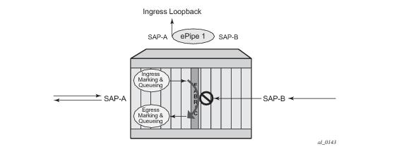
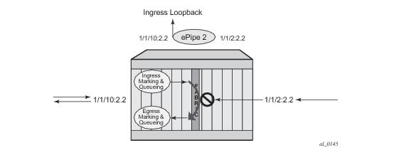
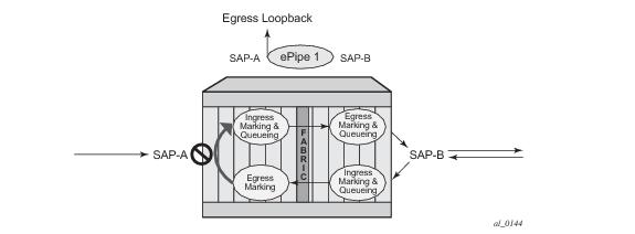
Essentially an ingress loopback function will isolate the SAP or MPLS SDP Binding from the rest of the service. The Figure 9 uses a simple ePipe service to illustrate the various touch points and processing that occurs on a packet that is processed by an ingress loopback as it moves through the network element.
Figure 9: Ingress Loopback
An egress loopback configured on the entity will have the following effects on the forwarding for the entity.
In the case of the egress loopback the SAP or MPLS SDP Binding is not isolated from the rest of the service it remains part of the service and reflects traffic back into the service. Extreme care must be used when considering the application of an egress loopback in a VPLS or I-VPLS service. Since a VPLS service rely on MAC based forwarding any packet that arrives at an egress loopback will be reflected back into the service and use MAC based forwarding to apply the proper forwarding decision. If this is a live multipoint service with active endpoints this could have very negative effects on the service and the clients connected to this service. Even if the forwarding database is primed any broadcast, unknown or multicast that arrives in the service will arrive on the egress loopback and will be reflected back into the service causing at the very least duplication of all of this type of traffic.
Figure 10 uses a simple ePipe service to illustrate the various touch points and processing that occurs on a packet that is processed by an egress loopback as it moves through the network element. Egress processing will not perform queuing functions on the egress it will only perform the functions of the forwarding plane like remarking.
Figure 10: Egress Loopback
The operational state of the SAP or MPLS SDP Binding will not change as a result of the loopback function. This means a SAP or MPLS SDP Binding that is operationally up will not change state strictly because of the loopback be started or stopped. Of course control protocols that are attempting to gain access via the entity that is not allowing packets to enter the service will eventually time out.
Care must be taken when considering the use of control protocols in a service with enabled loopbacks. The operator must be very aware of the impact that interrupting control protocols can have on the state of the SAP. When SAPs are dynamically created using a protocol or a protocol is required to maintain the operational state of the SAP, interruption of this control protocol will cause the SAP to fail. Other SAPs linking their state to a failed SAP will react to that failure as well. This loopback function is per Ethernet SAP or MPLS SDP Binding. This means that all traffic that is not extracted and sent to the CPM prior to the loopback process will all be looped back to in the direction it was received, or in the case of VPLS, back into the service. All service based control protocols that are included with this service should be removed to ensure the loopback process is handling the packets and not some other function on the node that can extract the control protocol but never respond because the service is block. However, there may be instances where an operator would want to continue to run control protocols for the service during a loopback. For example, Down MEPs on an Ethernet SAP could continue to process ETH-CFM packets if the loopback is on the mate Ethernet SAP and was configured as an egress loopback.
By default no MAC swap functions are performed. Options are available to allow for various MAC swap functions. Table 2 lists the various options and functions based on the configured
mac-swap and associated options.
 
Only the outer layer-two header can be manipulated.
In order for the loopback function to operate the service, the SAP/ MPLS SDP Binding, the port or LAG must be operational. In the case of a LAG the LAG must have members port that are operational. If the port over which the entity is configured is not operational or the LAG has no configured members the loopback function will not loopback traffic.
In order to configure this functionality the operator is required to us use the tools hierarchy. In this specific case, the loopback tools supporting this functionality may be configured through CLI or through SNMP. However, these commands are never resident in the configuration. This means the loopback will survive high availability events that cause one CPM to change from standby to active, as well as ISSU function or IOM resets (hard or soft). However the function will not survive a complete node reboot.
In the case on SNMP it is possible to configure a static mac address for the mac swap function without actually invoking the mac-swap. This is not possible through the CLI.
This function requires a minimum of IOM3/IMM.
This feature is mutually exclusive with functions that use mirroring.
Figure 11 shows an example for placing sap 1/1/10:2.2 in service id 2 (an epipe) in an active loopback mode with a mac-swap for all broadcast and multicast destined packets.
Figure 11: Active Loopback Mode
show service id 2 base
 
===============================================================================
Service Basic Information
===============================================================================
Service Id        : 2                   Vpn Id            : 0
Service Type      : Epipe
Name              : (Not Specified)
Description       : (Not Specified)
Customer Id       : 1                   Creation Origin   : manual
Last Status Change: 07/08/2013 09:57:02
Last Mgmt Change  : 07/08/2013 09:56:49
Admin State       : Up                  Oper State        : Up
MTU               : 1514
Vc Switching      : False
SAP Count         : 2                   SDP Bind Count    : 0
Per Svc Hashing   : Disabled
Force QTag Fwd    : Disabled
 
-------------------------------------------------------------------------------
Service Access & Destination Points
-------------------------------------------------------------------------------
Identifier                               Type         AdmMTU  OprMTU  Adm  Opr
-------------------------------------------------------------------------------
sap:1/1/2:2.2                            qinq         1522    1522    Up   Up
sap:1/1/10:2.2                           qinq         1522    1522    Up   Up
===============================================================================
 
tools perform service id 2 loopback start sap 1/1/10:2.2 ingress mac-swap mac 00:00:00:00:00:88
 
tools dump service loopback
===============================================================================
Service Ethernet Loopback Points
===============================================================================
Identifier                               Svc ID      Type  Swap    Swap    Oper
                                                           Unicast Mlt/Br
-------------------------------------------------------------------------------
SAP 1/1/10:2.2 qinq                      2           ingr  SA<->DA static  up
-------------------------------------------------------------------------------
No. of Service ethernet loopback points: 1
=============================================================================== 
 
tools dump service id 2 loopback sap 1/1/10:2.2
 
===============================================================================
Service ID 2 SAP 1/1/10:2.2 Loopback
===============================================================================
Identifier (SAP)      : 1/1/10:2.2 qinq
Service ID            : 2
Type                  : Ingress
MAC Swap
  Unicast             : SA<->DA
  Multicast/Broadcast : Static
  Static MAC          : 00:00:00:00:00:88
SAP Oper State        : Up
 
-------------------------------------------------------------------------------
Sap Statistics
-------------------------------------------------------------------------------
Last Cleared Time     : N/A
 
                        Packets                 Octets
CPM Ingress           : 491790                  46721290
 
Forwarding Engine Stats
Dropped               : 0                       0
Off. HiPrio           : 0                       0
Off. LowPrio          : 0                       0
Off. Uncolor          : 0                       0
Off. Managed          : 0                       0
 
Queueing Stats(Ingress QoS Policy 1)
Dro. HiPrio           : 0                       0
Dro. LowPrio          : 0                       0
For. InProf           : 0                       0
For. OutProf          : 0                       0
 
Queueing Stats(Egress QoS Policy 1)
Dro. InProf           : 0                       0
Dro. OutProf          : 0                       0
For. InProf           : 0                       0
For. OutProf          : 0                       0
-------------------------------------------------------------------------------
===============================================================================
To stop the loopback, a simple stop command is required.
tools perform service id 2 loopback stop sap 1/1/10:2.2
 
Class-Based Forwarding
 
Application of Class-Based Forwarding over RSVP LSPs
Class based forwarding over RSVP LSPs allows a service packet to be forwarded over a specific RSVP LSP, part of an SDP, based on its ingress determined forwarding class. The LSP selected depends on the operational status and load-balancing algorithms used for ECMP and LAG spraying.
Figure 12: Class-Based Forwarding over SDP LSPs
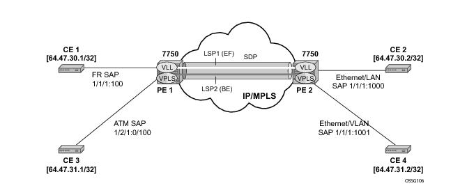
Figure 12 illustrates the use of class-based forwarding to direct packets of a service to specific RSVP or static LSPs that are part of the same SDP based on the packets' forwarding class. The forwarding class of the packet is the one assigned to the packet as a result of applying the ingress QoS policy to the service SAP. The VLL service packets are all classified into the “ef” forwarding class and those that are destined to PE2 are forwarded over LSP1. Multicast and broadcast are classified into the “be” class and are forwarded over LSP2.
This feature allows service providers to dedicate specific LSPs with a determined level of traffic engineering and protection to select service packets. For example, packets of a VoIP service are assigned the “ef” class to expedite their forwarding but are also sent over carefully traffic-engineered and FRR-protected LSP paths across the service provider network.
 
Operation of Class-Based Forwarding over RSVP LSPs
The 7750 SR class-based forwarding feature applies to a set of LSPs that are part of the same SDP. Each LSP must be configured as part of an SDP specifying the forwarding classes it will support. A forwarding class can only be assigned to one LSP in a given SDP, meaning that only one LSP within an SDP will support a given class of service. However, multiple classes of services can be assigned to an LSP. Both RSVP and static LSPs are allowed. All subclasses will be assigned to the same LSP as the parent forwarding class.
When a service packet is received at an ingress SAP, it is classified into one of the eight 7750 SR forwarding classes. If the packet will leave the SR on an SDP that is configured for class-based forwarding, the outgoing LSP will be selected based on the packet's forwarding class. Each SDP has a default LSP. The default LSP is used to forward a received packet that was classified at the ingress SAP into a forwarding class for which the SDP does not have an explicitly-configured LSP association. It is also used to forward a received packet if the LSP supporting its forwarding class is down. Note that the SDP goes down if the default LSP is down.
Class-based forwarding can be applied to all services supported by the 7750 SR. For VPLS services, explicit FC-to-LSP mappings are used for known unicast packets. Multicast and broadcast packets use the default LSP. There is a per-SDP user configuration that optionally overrides this behavior to specify an LSP to be used for multicast/broadcast packets.
VLL service packets are forwarded based on their forwarding class only if shared queuing is enabled on the ingress SAP. Shared queuing must be enabled on the VLL ingress SAP if class-forwarding is enabled on the SDP the service is bound to. Otherwise, the VLL packets will be forwarded to the LSP which is the result of hashing the VLL service ID. Since there are eight entries in the ECMP table for an SDP, one LSP ID for each forwarding class, the resulting load balancing of VLL service ID is weighted by the number of times an LSP appears on that table. For instance, if there are eight LSPs, the result of the hashing will be similar to when class based forwarding is disabled on the SDP. If there are fewer LSPs, then the LSPs which were mapped to more than one forwarding class, including the default LSP, will have proportionally more VLL services forwarding to them.
Note that only user packets are forwarded based on their forwarding class. OAM packets are forwarded in the same way as an SDP with class-based forwarding disabled. In other words, LSP ping and LSP trace messages are queued in the queue corresponding to the forwarding class specified by the user and are forwarded over the LSP being tested. Service and SDP OAM packets, such as, service ping, VCCV ping, and SDP ping, are queued in the queue corresponding to the forwarding class specified by the user and forwarded over the first available LSP.
Class-based forwarding is not supported for protocol packets tunneled through an SDP. All packets are forwarded over the default LSP.
Class-based forwarding is not supported on a spoke SDP used for termination on an IES or VPRN service. All packets are forwarded over the default LSP.
Multi-Service Sites
A customer site can be designated a multi-service site where a single scheduler policy is applied to all SAPs associated with the site while retaining per-service and per-forwarding class shaping and policing. The SAPs associated with the multi-service site can be on a single port or on a single slot. The SAPs in a multi-service site cannot span slots.
Multi-service sites are anchor points to create an ingress and egress virtual scheduler hierarchy. When a site is created, it must be assigned to a chassis slot or port with the exception of the 7750 SR-1 in which the slot is set to 1. When scheduler policies are defined for ingress and egress, the scheduler names contained in each policy are created according to the parameters defined in the policy. Multi-service customer sites exist for the sole purpose of creating a virtual scheduler hierarchy and making it available to queues on multiple Service Access Points (SAPs).
The scheduler policy association with the customer site normally prevents the scheduler policy from being deleted until after the scheduler policy is removed from the customer site.
When the multi-service customer site is created, an ingress and egress scheduler policy association does not exist. This does not prevent the site from being assigned to a chassis slot or prevent service SAP assignment. After the site has been created, the ingress and egress scheduler policy associations can be assigned or removed at any time.
Each customer site must have a unique name within the context of the customer. Modifications made to an existing site immediately affect all SAPs associated with the site. Changing a scheduler policy association can cause new schedulers to be created and existing queues on the SAPs to no longer be orphaned. Existing schedulers on the site may cease to exist, causing queues relying on that scheduler to be orphaned.
G.8031 Protected Ethernet Tunnels
Alcatel-Lucent implementation of Ethernet Tunnels offers ITU-T G.8031 specification compliance to achieve 50 ms resiliency for failures in a native Ethernet backbone for native Layer 2 networks.
Ethernet Automatic Protection Switching (APS) as defined in ITU-T recommends G.8031 provides a linear 1:1 or 1+1 protection switching mechanism for VLAN-based Ethernet networks. The OS implementation of G.8031 supports 1:1 linear protection through implementation of point-to-point Ethernet Tunnels providing a working and protecting Ethernet circuit, where the path providing the protection is always available through health-monitoring. The 1:1 model is common practice for packet based services since it makes best use of available bandwidth.
Within each path, Y.1731 Maintenance Entity Group (MEG) Endpoints (MEPs) are used to exchange APS-specific information (specifically to co-ordinate switchovers) as well as optionally fast Continuity Check Messages (CCM) providing an inherent fault detection mechanism as part of the protocol. Failure detection of a working path by one of the mechanisms triggers to move from working to protecting circuits. Upon failure, re-convergence times are a dependent on the failure detection mechanisms. In the case of Y.1731, the CCM transmit interval determines the response time. The OS supports message timers as low as 10 milliseconds so the restoration times are comparable to SONET/SDH. Alternatively, 802.3ah (Ethernet in the First Mile) or simple Loss of Signal can act as a trigger for a protection switch where appropriate.
Revertive or nonrevertive behavior can be configured based on service provider environment. Revertive behavior is commonly deployed since it restores the traffic to a predictable state.
Ethernet APS can be configured on any port configured for access mode using dot1q or Q-in-Q encapsulation enabling support for Ethernet APS protected services on the service edge towards the customer site, or within the Ethernet backbone. ELINE, ELAN, and ETREE services can be afforded Ethernet APS protection and, although the Ethernet Tunnel providing the protection has a working/protecting path that is presented to the service as a single logical entity to the service layer. The intention of this is to cause minimum disruption to the service during Ethernet APS failure detection and recovery.
Figure 13: Ethernet Protected Ethernet Tunnel Example
Figure 14: PBB G.8031 Protected Ethernet Tunnel Example
In the implementation, the Ethernet tunnel is a logical interface for a SAP defined Layer 2 service similar to a LAG. The implementation offers ITU G.8031 1:1 compliance as well as some added capabilities such as fate sharing and emulated LAG support.
It is important that the configuration for the various services does not change when a new Ethernet tunneling type is introduced on the backbone side. This is achieved by using a SAP to map the eth-tunnel object into service instance.
The member port and control tag defined under each eth-tunnel path are then used for encapsulating and forwarding the CCMs and the G.8031 PDUs used for protection function, the latter frames being sent only on the secondary path. The configuration of the active path is also used to instantiate the SAP object in the forwarding plane.
If a failure of a link or node affects the primary eth-tunnel path, the services will fail to receive the CC messages exchanged on that path or will receive a fault indication from the link layer OAM module.
For fault detection using CCMs, a number of 3.5 CC intervals plus a configurable hold-off timer must be missed for a fault to be declared on the associated path. The latter mechanism is required to accommodate the existence of additional 50 ms resiliency mechanism in the optical layer. After it received the fault indication, the protection module will declare the associated path down, then sends an indication to the remote protection module to switch the transmit direction to the backup path.
In order to address unidirectional failures, the RDI bit will be set in CC messages transmitted in the reverse direction upon detection of failure at the receiving service. The same applies for link layer OAM. Until the protection switch indication arrives from the remote node, the local node will continue to receive frames from both primary and backup paths to avoid the loss of in-flight packets.
In case of direct connectivity between the nodes, there is no need to use Ethernet CCM messaging for liveliness detection. Link level detection mechanisms like LoS (Loss of Signal) or IEEE 802.3ah link layer OAM can be used to detect link or nodal failure. This can be achieved by not provisioning a MEP on the primary path.
Using the Ethernet Tunnel as a building block for Ethernet APS protection it is possible to provide different protection schemes with different fate-dependency; or indeed to mix protected and non-protected services on the same physical port.
The simplest model is the fate-independent model where each Ethernet Tunnel supports its own protection using Y.1731 CCMs for example. In this case a single VLAN Tag may be used for control and data traffic. In cases where Ethernet Tunnels can be guaranteed to share a common physical path, it is possible to implement a fate-sharing model. This approach provides the advantage of reducing the amount of Ethernet OAM signaling because only one control tag determines the fate of many user tags.
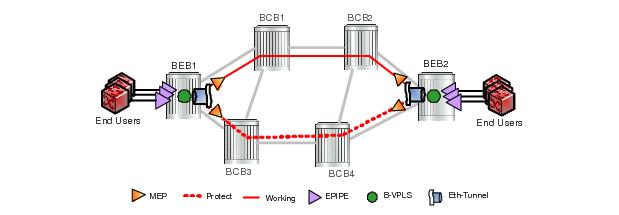
Epipe using BGP-MH site support for ethernet tunnels (see Epipe Using BGP-MH Site Support for Ethernet Tunnels) offers an enhancement to Ethernet Tunnels enabling an Ethernet edge device using G.8031 to support Multi-chassis redundancy for Epipe Services. The G.8031 device configuration is standard on the Ethernet edge device, but the active link is controlled by BGP-Multihoming just as with VPLS services. This Epipe feature offers a standards-based alternative for mulithomed access.
Figure 15: PBB Fate-Independent Ethernet Tunnels
Figure 16: PBB Fate Sharing Ethernet Tunnels
One of the advantages of access redundancy using Ethernet APS is that because it operates at the VLAN level protection mechanisms can be varied between services supported on the physical port. For example, it is possible to provide a protected service for “Premium” customers and also provide non-protected services for “Standard” users on the same physical port.
 
OAM Considerations
Ethernet CFM can be enabled on each individual path under an Ethernet tunnel. Only down MEPs can be configured on each of them and CCM sessions can be enabled to monitor the liveliness of the path using interval as low as 10 msec. Different CCM intervals can be supported on the primary and secondary paths in an Ethernet tunnel.
MEPs can still be configured under the services independent of the Ethernet Tunnels.
The following rules control the interaction between the MEP defined under the eth-tunnel path and the MEP defined in the service:
 
QoS Considerations
When Ethernet tunnel is configured on two member ports located on different IOMs, the SAP queues and virtual schedulers will be created with the actual parameters on each IOM.
The protection mode '8031-1to1' (default) activates only the primary path at any point in time, guaranteeing the use of the desired QoS resources.
Ethernet tunnel CC messages transmitted over the SAP queues using the default egress QoS policy will use NC (network class) as a forwarding class. If user traffic is assigned to the NC forwarding class, it will compete for the same bandwidth resources with the Ethernet CCMs. As CCM loss could lead to unnecessary bouncing of the Ethernet tunnel, congestion of the queues associated with the NC traffic should be avoided. The operator must configure different QoS Policies to avoid congestion for the CCM forwarding class by controlling the amount of traffic assigned into the corresponding queue.
 
Mirroring and Lawful Intercept Considerations
Mirroring and Lawful Intercept (LI) cannot use the eth-tunnel as a source. Also, a SAP configured on an eth-tunnel cannot be used as mirror destination. The CLI blocks the above options. The SAP configured on the eth-tunnel, a filter associated with it and the member ports in the eth-tunnel> path context can be used as mirror and LI source.
 
Support Service and Solution Combinations
The Ethernet tunnels are supported Layer 2 service VLL, VPLS and B-VPLS instances. The following considerations apply:
 
LAG Emulation using Ethernet Tunnels
Ethernet Tunnels can provide G.8031 Ethernet APS protection as described in G.8031 Protected Ethernet Tunnels, or they can operate in a load-sharing manner providing an emulated LAG function. Moreover, as multiple Ethernet Tunnels can be provisioned on the same physical link(s), it is possible that two physical links could support one or more Ethernet Tunnels supporting APS protection for protected services whilst concurrently supporting one or more Ethernet Tunnels in load-sharing mode for non-protected services.
When Ethernet Tunnels have the protection type set to load-sharing, the precedence is configured to secondary, making the tunnels equal in order to implement load-sharing capability. A path threshold parameter allows the load-sharing group to be declared down if the number of paths drops equal to or lower than the threshold value. The ‘lag-emulation’ context provides access to conventional LAG parameters such as the adapt-qos mode (link or distributed bandwidth distribution) and per-fp-ing-queuing to ensure that only one ingress queue is instantiated for every physical link supported on the same FP complex.
A typical use case for LAG emulation is to allow unprotected Ethernet services to capitalize on the LAG capability. RSTP and MSTP can also be used to network VPLS or B-VPLS over the Ethernet tunnels. LAG Emulation is also recommended when you use BGP-MH site support for ethernet tunnels.
G.8032 Ethernet Ring Protection Switching
Ethernet ring protection switching offers ITU-T G.8032 specification compliance to achieve resiliency for Ethernet Layer 2 networks. Similar to G.8031 linear protection (also called Automatic Protection Switching (APS)), G.8032 (Ethernet-ring) is built on Ethernet OAM and often referred to as Ring Automatic Protection Switching (R-APS).
Ethernet-rings are supported on VPLS SAPs (VPLS, I-VPLS, B-VPLS). VPLS services supporting Rings SAPs can connect to other rings and Ethernet service using VPLS and R-VPLS SAPs. Ethernet-rings enables rings for core network or access network resiliency. A single point of interconnection to other services is supported. The Ethernet-ring service is a VLAN service providing protection for ring topologies and the ability to interact with other protection mechanisms for overall service protection. This ensures failures detected by Ethernet-ring only result in R-APS switchover when the lower layer cannot recover and that higher layers are isolated from the failure.
Rings are preferred in data networks where the native connectivity is laid out in a ring or there is a requirement for simple resilient LAN services. Due to the symmetry and the simple topology, rings are viewed a good solution for access and core networks where resilient LANS are required. The Alcatel-lucent implementation can be used for interconnecting access rings and to provide traffic engineered backbone rings.
Ethernet-rings use one VID per control per ring instance and use one (typically) or multiple VIDs for data instances per control instance. A dedicated control VLAN (ERP VLAN) is used to run the protocol on the control VID. G.8032 controls the active state for the data VLANs (ring data instances) associated with a control instance. Multiple control instances allow logically separate rings on the same topology. The Alcatel-lucent implementation supports DOT1q, QinQ and PBB encapsulation for data ring instances. The control channel supports dot1q and QinQ encapsulation. Note that the control channel can support DOT1Q while the data channels use queuing if the global configure>system>ethernet>new-qinq-untagged-sap command is enabled.
 
Overview of G.8032 Operation
R-APS messages that carry the G.8032 protocol are sent on dedicated protocol VLAN called ERP VLAN (or Ring Control Instance). In a revertive case, G.8032 Protocol ensures that one Ring Protection Link (RPL) owner blocks the RPL link. R-APS messages are periodically sent around in both directions to inform other nodes in the Ring about the blocked port in the RPL owner node. In non-revertive mode any link may be the RPL. Y.1731 Ethernet OAM CC is the basis of the RAPs messages. Y.1731 CC messages are typically used by nodes in the ring to monitor the health of each link in the ring in both directions. However CC messages are not mandatory. Other link layer mechanisms could be considered – for example LOS (Loss of Signal) when the nodes are directly connected.
Initially each Ring Node blocks one of its links and notifies other nodes in the ring about the blocked link. Once a ring node in the ring learns that another link is blocked, the node unblocks its blocked link possibly causing FDB flush in all links of the ring for the affected service VLANs, controlled by the ring control instance. This procedure results in unblocking all links but the one link and the ring normal (or idle) state is reached. In revertive mode the RPL link will be the link that is blocked when all links are operable after the revert time. In non-revertive mode the RPL link is no different that other ring links. Revertive mode offers predictability particularly when there are multiple ring instances and the operator can control which links are block on the different instances. Each time there is a topology change that affects Reachability, the nodes may flush the FDB and MAC learning takes place for the affected service VLANs, allowing forwarding of packets to continue. Figure 17 depicts this operational state:
 
Figure 17: 0-1 G.8032 Ring in the Initial State
When a ring failure occurs, a node or nodes detecting the failure (enabled by Y.1731 OAM CC monitoring) send R-APS message in both directions. This allows the nodes at both ends of the failed link to block forwarding to the failed link preventing it from becoming active. In revertive mode, the RPL Owner then unblocks the previously blocked RPL and triggers FDB flush for all nodes for the affected service instances. The ring is now in protecting state and full ring connectivity is restored. MAC learning takes place to allow Layer 2 packet forwarding on a ring. The following picture depicts the failed link scenario.
 
Figure 18: 0-1 G.8032 Ring in the Protecting State
Once the failed link recovers, the nodes that blocked the link again send the R-APS messages indicating no failure this time. This in turn triggers RPL Owner to block the RPL link and indicate the Blocked RPL link the ring in R-APS message, which when received by the nodes at the recovered link cause them to unblock that link and restore connectivity (again all nodes in the ring perform FBD Flush and MAC learning takes place). The ring is back in the normal (or idle) state.
Within each path, Y.1731 Maintenance Entity Group (MEG) Endpoints (MEPs) are used to exchange R-APS specific information (specifically to co-ordinate switchovers) as well as optionally fast Continuity Check Messages (CCM) providing an inherent fault detection mechanism as part of the protocol. Failure detection of a ring path by one of the mechanisms triggers to activate the protection links. Upon failure, re-convergence times are a dependent on the failure detection mechanisms. In the case of Y.1731, the CCM transmit interval determines the response time. The 7x507210 SAS supports message timers as low as 10 milliseconds (also 100 ms) so the restoration times are comparable to SONET/SDH. Alternatively, 802.3ah (Ethernet in the First Mile) or simple Loss of Signal can act as a trigger for a protection switch where appropriate. In case of direct connectivity between the nodes, there is no need to use Ethernet CC messaging for liveliness detection.
Revertive and non-revertive behaviors are supported. The Ring protection link (RPL) is configured and Ethernet-rings can be configured to revert to the RPL upon recovery.
G.8032 supports multiple data channels (VIDs) or instances per ring control instance (R-APS tag). G.8032 also supports multiple control instances such that each instance can support RPLs on different links providing for a load balancing capability however once services have been assigned to one instance the rest of the services that need to be interconnected to those services must be on the same instance. In other words each data instance is a separate data VLAN on the same physical topology. When there is any one link failure or any one node failure in the ring, G.8032 protocols are capable of restoring traffic between all remaining nodes in these data instances.
Ethernet R-APS can be configured on any port configured for access mode using dot1q, q-in-q encapsulation enabling support for Ethernet R-APS protected services on the service edge towards the customer site, or within the Ethernet backbone. ELINE, ELAN, and ETREE services can be afforded Ethernet R-APS protection and, although the Ethernet Ring providing the protection uses a ring for protection the services are configured independent of the Ring properties. The intention of this is to cause minimum disruption to the service during Ethernet R-APS failure detection and recovery.
In the implementation, the Ethernet Ring is built from a VPLS service on each node with VPLS SAPs that provides Ring path with SAPs. As a result, most of the VPLS SAP features are available on Ethernet rings if desired. This results in a fairly feature rich ring service.
The control tag defined under each Ethernet-ring is used for encapsulating and forwarding the CCMs and the G.8032 messages used for the protection function. If a failure of a link or node affects an active Ethernet ring segment, the services will fail to receive the CCMs exchanged on that segment or will receive a fault indication from the Link Layer OAM module. CCMs are optional but MEPs are always configured to provide G.8032 control.
For fault detection using CCMs three CC messages plus a configurable hold-off timer must be missed for a fault to be declared on the associated path. The latter mechanism is required to accommodate the existence of additional, 50 ms resiliency mechanism in the optical layer. After it receives the fault indication, the protection module will declare the associated ring link down and the G.8032 state machine will send the appropriate messages to open the RPL and flush the learned addresses.
Flushing is triggered by the G.8032 state machine and the 7x50 implementation allows flooding of traffic during the flushing interval to expedite traffic recovery.
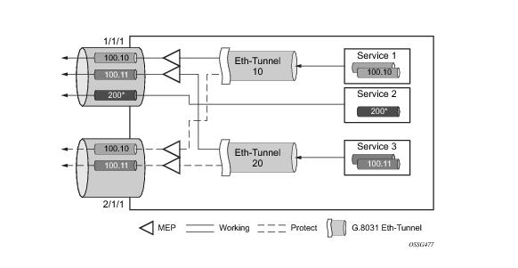
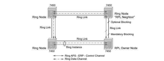
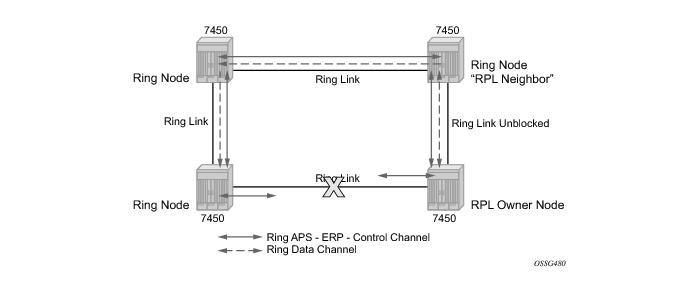
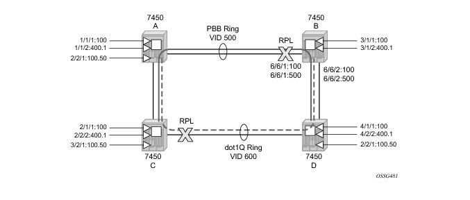
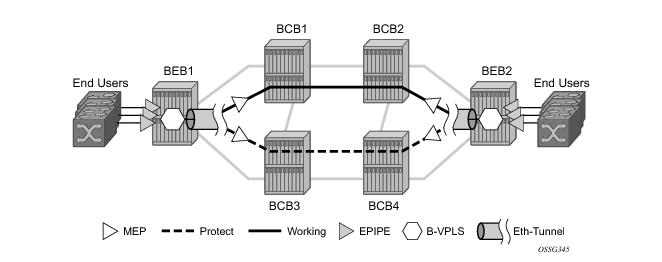
Figure 19 illustrates a resilient Ring Service. In the example a PBB ring (solid line) using VID 500 carries 2 service VLANs on I-SID 1000 and 1001 for Service VIDs (Dot1q 100 and QinQ 400.1 respectively.) The RPL for the PBB ring is between A and B where B is the RPL owner. Also illustrated is a QinQ service on the (dotted line) ring that uses Dot1q VID 600 for the ring to connect service VLAN 100.50. The two rings have RPLs on different nodes which allow a form of load balancing. The example serves to illustrate that service encapsulations and ring encapsulation can be mixed in various combinations. Also note that neither of the rings is closed loop. A ring can restore connectivity when any one node or link fails to all remaining nodes within the 50 ms transfer time (signaling time after detection).
Figure 19: 0-3 Ring Example
Sample Configuration:
configure eth-ring 1
    description  "Ring PBB BLUE on Node B"
    revert-time 100
    guard-time 5
    ccm-hold-time down 100 up 200
    rpl-node owner
    path a  6/6/1 raps-tag 100 								// CC Tag 100
        description "To A ring link"
        rpl-end
        eth-cfm
            mep 1 domain 1 association 1 direction down 
                  								// Control MEP
            no shutdown
            exit
        exit
        no shutdown 								// would allow protect switching 
                      								// in absence of the "force" cmd
    exit
    path b  6/6/2 raps-tag 100 								//Tag 100 
    description "to D Ring Link"
        eth-cfm
            mep 1 domain 1 association 1 direction down
            no shutdown
            exit
        exit
        no shutdown
    no shutdown
    exit
    service 
        vpls 10 customer 1 create 								// Ring APS SAPs
            description "Ring Control VID 100" 
                sap 6/6/1:100 eth-ring 1 create 
                             								// TAG for the Control Path a
            exit
                sap 6/6/2:100 eth-ring 1 create 
                             								// TAG for the Control Path b
            exit
        no shutdown
    exit
    service 
        vpls 40 customer 1 b-vpls create //Data Channel on Ring
        description "Ethernet Ring 1 VID 500" 
            sap 6/6/1:500 eth-ring 1 create 
                              								// TAG for the Data Channel Path a
        exit
            sap 6/6/2:500 eth-ring 1 create 
                              								// TAG for the Data Channel Path b
        exit
    exit
    service vpls 1000 i-vpls 								// CPE traffic 
    sap 3/1/1:100 create 								// CPE SAP 
        pbb
            backbone-vpls 40 isid 1000 
              exit 
        exit
    no shutdown
    exit
    service vpls 1001 i-vpls 								// CPE traffic 
    sap 3/1/2:400.1 create   								// CPE SAP 
        pbb
            backbone-vpls 40 isid 1001 
              exit 
        exit
    no shutdown
    exit
 
Ethernet Unnumbered Interfaces
The ability to configure Ethernet Unnumbered interfaces has been added to support some service types for IPv4. The unnumbered interface capability has been available for other interface types on SR OS. Unnumbered Ethernet allows point-to-point interfaces to borrow the address from other interfaces such as system or loopback interfaces.
This feature enables unnumbered interfaces for some routing protocols (IS-IS and OSPF). Support for routing is dependent on the respective routing protocol and service. This feature also adds support for both dynamic and static ARP for unnumbered Ethernet interfaces to allow interworking with unnumbered interfaces that may not support dynamic ARP.
The use of unnumbered interface has no effect on IPv6 routes but the unnumbered command must only be used in cases where IPv4 is active (IPv4 only and mixed IPv4/IPv6 environments). When using an unnumbered interface for IPv4, the loopback address used for the unnumbered interface must have IPv4 address. Also, interface type for the unnumbered interface will automatically be point-to-point.
 
Ethernet Ring Sub-Rings
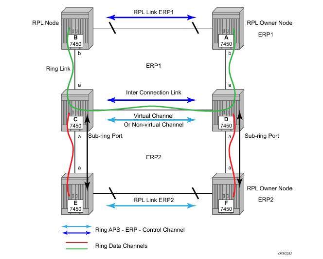
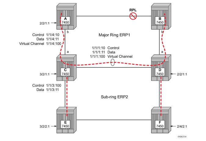
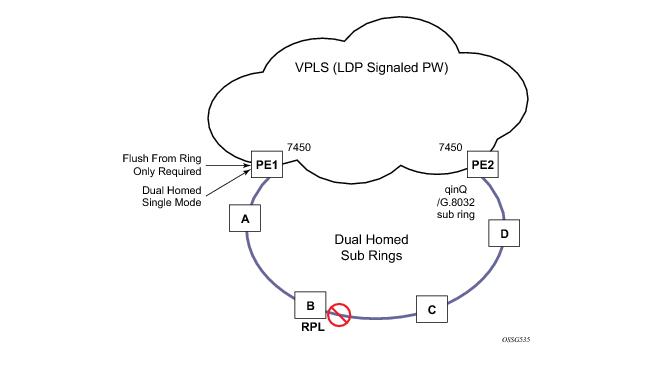
Ethernet Sub-Rings offer a dual redundant way to interconnect rings. The 7x50 supports Sub-Rings connected to major rings and a sub-ring connected to a VPLS (LDP based) for access rings support in VPLS networks. Figure 20 illustrates a Major ring and Sub Ring scenario. In this scenario, any link can fail in either ring (ERP1 or ERP2) and each ring is protected. Furthermore, the sub ring (ERP2) relies on the major Ring (ERP1) as part of its protection for the traffic from C and D. The nodes C and D are configured as inter connection nodes.
Figure 20: 0-4 G.8032 Sub-Ring
Sub-Rings and Major Rings run similar state machines for the ring logic, however there are some differences. When Sub-Rings protect a link, the flush messages are propagated to the major ring. (A special configuration allows control of this option on the 7x50.) When major rings change topology, the flush is propagated around the major ring and does not continue to any sub-rings. The reason for this is that Major Rings are completely connected but Sub-Rings are dependent on another ring or network for full connectivity. The topology changes need to be propagated to the other ring or network usually. Sub-Rings offer the same capabilities as major rings in terms of control and data so that all link resource may be utilized.
 
Virtual and Non-Virtual Channel
The 7x50 platform supports both the virtual channel and non-virtual channel for sub-ring control communication. In the virtual channel mode, a dedicated VID, other than the major ring RAPs control channel is configured as a data instance on the major ring. This allows the sub-ring control messages and state machine logic to behave similar to a major ring. In the non-virtual channel mode, the sub-ring is only connected by the RAPs control channels on the sub-ring itself. This mode offers slightly less redundancy in the RAPs messaging than the virtual channel mode since sub-ring RAPs messages are not propagated across the major ring. When non-virtual link is configured, the protocol allows RPL messages over the sub-ring blocked link.
Figure 21: 0-5 Sub-Ring Configuration Example
Sub-ring configuration is similar to major ring configuration and consists of three parts: Ethernet-ring instance configuration, control VPLS configuration and data VPLS configuration (data instance or data channel). The Ethernet-ring configuration of a sub-ring is tied to a major ring and only one path is allowed. Note that a split horizon group is mandatory to ensure that Sub-Ring control messages from the major ring are only passed to the sub-ring control.
The data VPLS can be configured on the major ring, and in the example, shares the same VID (SAP encapsulation) on both the major ring and the sub-ring to keep data on the same VLAN ID everywhere. (Note that just like other services in the 7x50 the encapsulation VID is controlled by SAP configuration and the association to the controlling ring is by the Ethernet-ring, ring-id.)
The following illustrates a sample sub-ring configuration on Node C:
eth-ring 2
        description "Ethernet Sub Ring on Ring 1"
        sub-ring virtual-link // Using a virtual link
            interconnect ring-id 1 // Link to Major Ring 1
                propagate-topology-change 
            exit
        exit
        path a 1/1/3 raps-tag 100 // Ring control uses VID 100
            eth-cfm
                mep 9 domain 1 association 4
                    ccm-enable
                    control-mep
                    no shutdown
                exit
            exit
            no shutdown
        exit
        no shutdown
    exit
Note that if the sub-ring been configured as a non-virtual-link, the sub-ring configuration above and on all the other sub-ring nodes for this sub-ring would become:
        sub-ring non-virtual-link // Not using a virtual link
 
# Control Channel for the Major Ring ERP1 illustrates that Major ring 
# control is still separate from Sub-ring control
  vpls 10 customer 1 create
      description "Control VID 10 for Ring 1 Major Ring"
      stp shutdown
      sap 1/1/1:10 eth-ring 1 create
          stp shutdown
          exit
      sap 1/1/4:10 eth-ring 1 create
          stp shutdown 
          exit
      no shutdown
  exit 
 
# Data configuration for the Sub-Ring
 
  vpls 11 customer 1 create
      description "Data on VID 11 for Ring 1"
      stp shutdown 
      sap 1/1/1:11 eth-ring 1 create // VID 11 used for ring
          stp shutdown 
      exit
      sap 1/1/4:11 eth-ring 1 create
          stp shutdown 
      exit
      sap 1/1/3:11 eth-ring 2 create // Sub-ring data
          stp shutdown 
      exit
      sap 3/2/1:1 create 
      description "Local Data SAP"
          stp shutdown 
      no shutdown
  exit
 
# Control Channel for the Sub-Ring using a virtual link. This is 
# a data channel as far as Ring 1 configuration. Other Ring 1 
# nodes also need this VID to be configured. 
 
  vpls 100 customer 1 create
      description "Control VID 100 for Ring 2 Interconnection"
      split-horizon-group "s1" create //Ring Split horizon Group
      exit
      stp shutdown 
      sap 1/1/1:100 split-horizon-group "s1" eth-ring 1 create
          stp shutdown 
      exit
      sap 1/1/4:100 split-horizon-group "s1" eth-ring 1 create
          stp shutdown 
      exit
      sap 1/1/3:100 eth-ring 2 create
          stp shutdown 
      exit
      no shutdown
  exit 
Note that had the sub-ring been configured as a non-virtual-link the configuration above would become:
  vpls 100 customer 1 create
      description "Control VID 100 for Ring 2 Interconnection"
      sap 1/1/3:100 eth-ring 2 create
          stp shutdown 
      exit
      no shutdown
  exit 
 
Figure 22: 0-6 Sub-Ring Homed to VPLS
The 7x50 platform allows for a special configuration of the non-virtual link sub-ring that can be homed to a VPLS service illustrated in Figure 22. This is an economical way to have a redundant ring connection to a VPLS service. This is currently supported only for dot1Q and QinQ sub-rings and only on LDP based VPLS. The primary application for this is access rings that require resiliency. This configuration shows the configuration for a sub-ring at an interconnection node without a virtual channel and interconnected to a VPLS. A VPLS service 1 is used to terminate the ring control. The Ethernet ring data SAP appears in the associated LDP based VPLS service 5.
The following illustrates a sample sub-ring configuration for VPLS (at PE1):
eth-ring 1
      description "Ethernet Ring 1"
      guard-time 20
      no revert-time
      rpl-node nbr
      sub-ring non-virtual-link
          interconnect vpls // VPLS is interconnection type
              propagate-topology-change 
          exit
      exit
      path a 1/1/3 raps-tag 1.1
          description "Ethernet Ring : 1 Path on LAG"
          eth-cfm
          mep 8 domain 1 association 8
               ccm-enable
               control-mep
               no shutdown
            exit
        exit
        no shutdown
    exit
    no shutdown
exit
 
# Configuration for the ring control interconnection termination:  
  vpls 1 customer 1 create
      description "Ring 1 Control termination"
      stp shutdown
      sap 1/1/3:1.1 eth-ring 1 create //path a control
          stp shutdown
      exit
      no shutdown
  exit
 
# Configuration for the ring data into the LDP based VPLS Service
 
  vpls 5 customer 1 create
      description "VPLS Service at PE1"
      stp
          no shutdown
      exit
      sap 1/1/3:2.2 eth-ring 1 create
          stp shutdown
      exit
      sap 1/1/5:1 create
      exit
      mesh-sdp 5001:5 create //sample LDP MPLS LSPs
      exit
      mesh-sdp 5005:5 create
      exit
      mesh-sdp 5006:5 create
      exit
          
      no shutdown
  exit
 
Figure 23: 0-7 Multi Ring Hierarchy
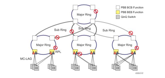
Ethernet-rings and sub-rings offer a way to build a scalable resilient Ethernet transport network. Figure 236 illustrates a hierarchical ring network using PBB where dual homed services are connected to a PBB based Ethernet ring network. The major rings are connected by sub-rings to the top level major ring. These sub-rings require virtual channel and will not work with non-virtual channel. Ring flushing is contained to major rings, or in the case of a sub-ring link or node failure, to the sub-ring and the directly attached major rings.
 
Lag Support
Ethernet-rings support LAG on Ethernet rings SAPS. However, the use of LAG impact the response time for resiliency. In many cases, the use of multiple ring instances each on a single link may be more suitable from a resiliency and QoS standpoint than using LAG on Ethernet rings in a given topology. If sub 100ms response is not required, LAG is an option for Ethernet-rings.
 
OAM Considerations
Ethernet CFM is enabled by configuring MEPs on each individual path under an Ethernet ring. Only down MEPs can be configured on each of them and optionally, CCM sessions can be enabled to monitor the liveliness of the path using interval of 10 or 100 msec. Different CCM intervals can be supported on the path a and path b in an Ethernet ring. CFM is optional if hardware supports Loss of Signal (LOS) for example, which is controlled by configuring
no-ccm-enable.
Up MEPs on service SAPs which multicast into he service and monitor the active path may be used to monitor services.
When Ethernet ring is configured on two ports located on different IOMs, the SAP queues and virtual schedulers will be created with the actual parameters on each IOM.
Ethernet ring CC messages transmitted over the SAP queues using the default egress QoS policy will use NC (network class) as a forwarding class. If user traffic is assigned to the NC forwarding class, it will compete for the same bandwidth resources with the Ethernet CCMs. As CCM loss could lead to unnecessary switching of the Ethernet ring, congestion of the queues associated with the NC traffic should be avoided. The operator must configure different QoS Policies to avoid congestion for the CCM forwarding class by controlling the amount of traffic assigned into the corresponding queue.
Details of the Ethernet ring applicability in the services solution can be found in the respective Layer 2 sections of the Services Guide.
 
Support Service and Solution Combinations
The Ethernet rings are supported Layer 2 service, VPLS, I-VPLS, R-VPLS and B-VPLS instances. The following considerations apply:
While Ethernet-rings is an IOM3 feature service SAPs may not be on IOM3 cards but this may affect recovery times during topology changes.
 
Internal Objects Created for L2TP and NAT
Some services such as L2TP LNS (L2TP Network Server) and NAT (Network Address Translation) automatically create service objects for internal use. In particular, an IES service with ID 2147483648 is created. In that service, or in configured VPRN services, service objects such as interfaces, SAPs and related objects can be automatically created for internal use.
Named objects reserved for internal use have a name that starts with “_tmnx_”. Objects with a numeric identifier created for internal use have an identifier from a reserved range.
The general rules for objects reserved for internal use:
Will appear in the output of info detail commands but will never be in the output of admin save [detail].
It may be possible to enter the CLI node of such an object, but it is not possible to change anything. It may also be possible to set the value of one of its objects to the current value with SNMP, but it will never be possible to change any value.
Service Creation Process Overview
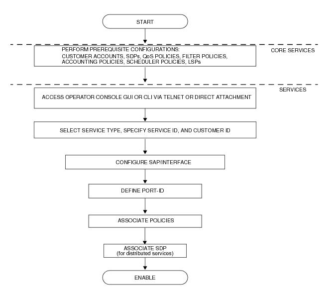
Figure 24 displays the overall process to provision core and subscriber services.
Figure 24: Service Creation and Implementation Flow
Deploying and Provisioning Services
The service model provides a logical and uniform way of constructing connectivity services. The basic steps for deploying and provisioning services can be broken down into three phases.
 
Phase 1: Core Network Construction
Before the services are provisioned, the following tasks should be completed:
 
Phase 2: Service Administration
Perform preliminary policy and SDP configurations to control traffic flow, operator access, and to manage fault conditions and alarm messages, the following tasks should be completed:
 
Phase 3: Service Provisioning
Provision the services on the SR-Series service edge routers by defining SAPs, binding policies to the SAPs, and then binding the service to appropriate SDPs as necessary. Refer to Configuring Customers on page 103 and Configuring an SDP on page 107.
Configuration Notes
This section describes service configuration caveats.
 
General
Service provisioning tasks can be logically separated into two main functional areas, core tasks and subscriber tasks and are typically performed prior to provisioning a subscriber service.
Core tasks include the following:
Subscriber services tasks include the following: