For feedback, use the following:
ipd_online_feedback@alcatel-lucent.com
Table of Contents Previous Next Index PDF


QoS Policies
In This Chapter
This chapter provides information about Quality of Service (QoS) policy management.
Topics in this chapter include:
QoS Overview
Routers are designed with Quality of Service (QoS) mechanisms on both ingress and egress to support multiple customers and multiple services per physical interface. The router has an extensive and flexible capabilities to classify, police, shape and mark traffic.
In the Alcatel-Lucent service router’s service model, a service is provisioned on the provider-edge (PE) equipment. Service data is encapsulated and then sent in a service tunnel to the far-end Alcatel-Lucent service router where the service data is delivered.
The operational theory of a service tunnel is that the encapsulation of the data between the two Alcatel Lucent service routers (such as the 7950 XRS, 7750 SR, 7710 SR, 7750 SR MG and 7450 ESS) appear like a Layer 2 path to the service data although it is really traversing an IP or IP/MPLS core. The tunnel from one edge device to the other edge device is provisioned with an encapsulation and the services are mapped to the tunnel that most appropriately supports the service needs.
The router supports eight forwarding classes internally named: Network-Control, High-1, Expedited, High-2, Low-1, Assured, Low-2 and Best-Effort. The forwarding classes are discussed in more detail in Forwarding Classes.
Router use QoS policies to control how QoS is handled at distinct points in the service delivery model within the device. There are different types of QoS policies that cater to the different QoS needs at each point in the service delivery model. QoS policies are defined in a global context in the router and only take effect when the policy is applied to a relevant entity.
QoS policies are uniquely identified with a policy ID number or name. Policy ID 1 or Policy ID “default” is reserved for the default policy which is used if no policy is explicitly applied.
The QoS policies within the router can be divided into three main types:
 
QoS Policies
Router QoS policies are applied on service ingress, service egress and network interfaces and define:
Classification rules for how traffic is mapped to queues
The router has 8K ingress and 8K egress queues per Flexible Fast Path complex which services a single MDA.
There are several types of QoS policies:
Service ingress QoS policies are applied to the customer-facing Service Access Points (SAPs) and map traffic to forwarding class queues on ingress. The mapping of traffic to queues can be based on combinations of customer QoS marking (IEEE 802.1p bits, DSCP, and TOS precedence), IP and MAC criteria. The characteristics of the forwarding class queues are defined within the policy as to the number of forwarding class queues for unicast traffic and the queue characteristics. There can be up to eight (8) unicast forwarding class queues in the policy; one for each forwarding class. A service ingress QoS policy also defines up to three (3) queues per forwarding class to be used for multipoint traffic for multipoint services. In the case of the VPLS, four types of forwarding are supported (which is not to be confused with forwarding classes); unicast, multicast, broadcast, and unknown. Multicast, broadcast, and unknown types are flooded to all destinations within the service while the unicast forwarding type is handled in a point-to-point fashion within the service.
Service egress QoS policies are applied to SAPs and map forwarding classes to service egress queues for a service. Up to 8 queues per service can be defined for the 8 forwarding classes. A service egress QoS policy also defines how to remark the forwarding class to IEEE 802.1p bits in the customer traffic.
Network QoS policies are applied to IP interfaces. On ingress, the policy applied to an IP interface maps incoming DSCP and EXP values to forwarding class and profile state for the traffic received from the core network. On egress, the policy maps forwarding class and profile state to DSCP and EXP values for traffic to be transmitted into the core network.
Network queue policies are applied on egress to network ports and channels and on ingress to MDAs. The policies define the forwarding class queue characteristics for these entities.
Service ingress, service egress, and network QoS policies are defined with a scope of either template or exclusive. Template policies can be applied to multiple SAPs or IP interfaces whereas exclusive policies can only be applied to a single entity.
One service ingress QoS policy and one service egress QoS policy can be applied to a specific SAP. One network QoS policy can be applied to a specific IP interface. A network QoS policy defines both ingress and egress behavior.
If no QoS policy is explicitly applied to a SAP or IP interface, a default QoS policy is applied.
 
A summary of the major functions performed by the QoS policies is listed in Table 2.
 
Packets are marked using QoS policies on edge devices. Invoking a QoS policy on a network port allows for the packets that match the policy criteria to be remarked.
 
 
Service and Network QoS Policies
The QoS mechanisms within the routers are specialized for the type of traffic on the interface. For customer interfaces, there is service ingress and egress traffic, and for network core interfaces, there is network ingress and network egress traffic (Figure 1).
 
Figure 1: 7750 SR Traffic Types
The router uses QoS policies applied to a SAP for a service or to an network port to define the queuing, queue attributes, and QoS marking/interpretation.
The router supports four types of service and network QoS policies:
 
Network QoS Policies
Network QoS policies define egress QoS marking and ingress QoS interpretation for traffic on core network IP interfaces. The router automatically creates egress queues for each of the forwarding classes on network IP interfaces.
A network QoS policy defines both the ingress and egress handling of QoS on the IP interface. The following functions are defined.
The required elements to be defined in a network QoS policy are:
Optional network QoS policy elements include:
Network policy ID 1 is reserved as the default network QoS policy. The default policy cannot be deleted or changed.
The default network QoS policy is applied to all network interfaces which do not have another network QoS policy explicitly assigned.
 
 
For network ingress, Table 4 and Table 5 list the default mapping of DSCP name and LSP EXP values to forwarding class and profile state for the default network QoS policy.
 
 
Network Queue QoS Policies
Network queue policies define the network forwarding class queue characteristics. Network queue policies are applied on egress on core network ports, channels and on ingress on MDAs. Network queue policies can be configured to use as many queues as needed This means that the number of queues can vary. Not all policies will use eight queues like the default network queue policy.
The queue characteristics that can be configured on a per-forwarding class basis are:
Network queue policies are identified with a unique policy name which conforms to the standard router alphanumeric naming conventions.
The system default network queue policy is named default and cannot be edited or deleted. Table 5 describes the default network queue policy definition.
 
 
Queue Parameters
This section describes the queue parameters provisioned on access and queues for QoS.
The queue parameters are:
 
Queue ID
The queue ID is used to uniquely identify the queue. The queue ID is only unique within the context of the QoS policy within which the queue is defined.
 
Unicast or Multipoint Queue
Currently, only VPLS services utilize multipoint ingress queues although IES services use multipoint ingress queues for multicast traffic alone when PIM is enabled on the service interface.
 
Queue Hardware Scheduler
The hardware scheduler for a queue dictates how it will be scheduled relative to other queues at the hardware level. When a queue is defined in a service ingress or service egress QoS policy, it is possible to explicitly define the hardware scheduler to use for the queue when it is applied to a SAP.
Being able to define a hardware scheduler is important as a single queue allows support for multiple forwarding classes. The default behavior is to automatically choose the expedited or non-expedited nature of the queue based on the forwarding classes mapped to it. As long as all forwarding classes mapped to the queue are expedited (nc, ef, h1 or h2), the queue will be treated as an expedited queue by the hardware schedulers. When any non-expedited forwarding classes are mapped to the queue (be, af, l1 or l2), the queue will be treated as best effort by the hardware schedulers.
The expedited hardware schedulers are used to enforce expedited access to internal switch fabric destinations.
 
Committed Information Rate
The committed information rate (CIR) for a queue performs two distinct functions:
1.
2.
All router queues support the concept of in-profile and out-of-profile. The network QoS policy applied at network egress determines how or if the profile state is marked in packets transmitted into the service core network. If the profile state is marked in the service core packets, out-of-profile packets are preferentially dropped over in-profile packets at congestion points in the core.
1.
Although the router is flexible in how the CIR can be configured, there are conventional ranges for the CIR based on the forwarding class of a queue. A service ingress queue associated with the high-priority class normally has the CIR threshold equal to the PIR rate although the router allows the CIR to be provisioned to any rate below the PIR should this behavior be required. If the service egress queue is associated with a best-effort class, the CIR threshold is normally set to zero; again the setting of this parameter is flexible.
The CIR for a service queue is provisioned on ingress and egress service queues within service ingress QoS policies and service egress QoS policies, respectively.
The CIR for network queues are defined within network queue policies based on the forwarding class. The CIR for the queues for the forwarding class are defined as a percentage of the network interface bandwidth.
 
Peak Information Rate
The peak information rate (PIR) defines the maximum rate at which packets are allowed to exit the queue. It does not specify the maximum rate at which packets may enter the queue; this is governed by the queue's ability to absorb bursts and is defined by its maximum burst size (MBS).
The actual transmission rate of a service queue depends on more than just its PIR. Each queue is competing for transmission bandwidth with other queues. Each queue's PIR, CIR and the relative importance of the scheduler serving the queue all combine to affect a queue's ability to transmit packets as discussed in Single Tier Scheduling.
The PIR is provisioned on ingress and egress service queues within service ingress QoS policies and service egress QoS policies, respectively.
The PIR for network queues are defined within network queue policies based on the forwarding class. The PIR for the queues for the forwarding class are defined as a percentage of the network interface bandwidth.
When defining the PIR for a queue, the value specified is the administrative PIR for the queue.The router has a number of native rates in hardware that it uses to determine the operational PIR for the queue. The user has some control over how the administrative PIR is converted to an operational PIR should the hardware not support the exact CIR and PIR values specified. The interpretation of the administrative PIR is discussed below in Adaptation Rule
 
Adaptation Rule
The adaptation rule provides the QoS provisioning system with the ability to adapt specific CIR and PIR defined administrative rates to the underlying capabilities of the hardware the queue will be created on to derive the operational rates. The administrative CIR and PIR rates are translated to actual operational rates enforced by the hardware queue. The rule provides a constraint used when the exact rate is not available due to hardware implementation trade-offs.
For the CIR and PIR parameters individually, the system will attempt to find the best operational rate depending on the defined constraint. The supported constraints are:
Depending on the hardware upon which the queue is provisioned, the actual operational CIR and PIR settings used by the queue will be dependant on the method the hardware uses to implement and represent the mechanisms that enforce the CIR and PIR rates.
The adaptation rule always assumes that the PIR (shaping parameter) on the queue is the most important rate. When multiple available hardware rates exist for a given CIR and PIR rate pair, the PIR constraint is always evaluated before the CIR.
The router 20 Gbps Input/Output Module (IOM) uses a rate step value to define the granularity for both the CIR and PIR rates The adaptation rule controls the method the system uses to choose the rate step based on the administrative rates defined by the rate command. The supported CIR and PIR values ranges and increments are summarized in Table 6.
The MDA hardware rate-step values are listed in Table 7 for all MDAs (except deep channel MDAs).
 
Rate Range (Rate Step x 0 to Rate Step x 127 and max)1

1
0 is unavailable for PIR
 

The MDA hardware rate-step values are listed below for deep channel MDAs (m1-choc12-sfp, m4-choc3-sfp, and m4-chds3). The table shows supported hardware rates and CIR/PIR values for ingress traffic from all MDAs/CMAs and egress traffic for all CMAs and deep channel MDAs.
 
0 to 1.3Gb/sec and (0 unavailable for PIR)
0 to 254Mb/sec and (0 unavailable for PIR)
0 to 65Mb/sec and (0 unavailable for PIR)

1
0 unavailable for PIR

To illustrate how the adaptation rule constraints minimum, maximum and closest are evaluated in determining the operational CIR or PIR for the router 20 Gbps IOM, assume there is a queue where the administrative CIR and PIR values are 401 Mbps and 403 Mbps, respectively. According to Table 6, since the PIR value is given precedence and is in the range of 0 to 635 Mbps, the hardware rate step of 5 Mbps is used.
If the adaptation rule is minimum, the operational CIR and PIR values will be 405 Mbps as it is the native hardware rate greater than or equal to the administrative CIR and PIR values.
If the adaptation rule is maximum, the operational CIR and PIR values will be 400 Mbps.
If the adaptation rule is closest, the operational CIR and PIR values will be 400 Mbps and 405 Mbps, respectively, as those are the closest matches for the administrative values that are even multiples of the 5 Mbps rate step.
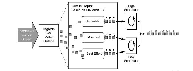
The hardware rate step values are for the queue CIR and PIR and have the maximum decrement value of 127.
The port rate is set in a VOQ and hence can use a maximum decrement value of 255.
 
 
Committed Burst Size
The committed burst size (CBS) parameters specify the amount of buffers that can be drawn from the reserved buffer portion of the queue’s buffer pool. Once the reserved buffers for a given queue have been used, the queue contends with other queues for additional buffer resources up to the maximum burst size.
The CBS is provisioned on ingress and egress service queues within service ingress QoS policies and service egress QoS policies, respectively. The CBS for a queue is specified in Kbytes.
The CBS for network queues are defined within network queue policies based on the forwarding class. The CBS for the queues for the forwarding class are defined as a percentage of buffer space for the pool.
 
Maximum Burst Size
The maximum burst size (MBS) parameter specifies the maximum queue depth to which a queue can grow. This parameter ensures that a customer that is massively or continuously over-subscribing the PIR of a queue will not consume all the available buffer resources. For high-priority forwarding class service queues, the MBS can be relatively smaller than the other forwarding class queues because the high-priority service packets are scheduled with priority over other service forwarding classes.
The MBS is provisioned on ingress and egress service queues within service ingress QoS policies and service egress QoS policies, respectively. The MBS for a queue is specified in Kbytes.
The MBS for network queues are defined within network queue policies based on the forwarding class. The MBS for the queues for the forwarding class are defined as a percentage of buffer space for the pool.
 
High-Priority Only Buffers
High priority (HP)-only buffers are defined on a queue and allow buffers to be reserved for traffic classified as high priority. When the queue depth reaches a specified level, only high-priority traffic can be enqueued. The HP-only reservation for a queue is defined as a percentage of the MBS value.
On service ingress, the HP-only reservation for a queue is defined in the service ingress QoS policy. High priority traffic is specified in the match criteria for the policy.
On service egress, the HP-only reservation for a queue is defined in the service egress QoS policy. Service egress queues are specified by forwarding class. High-priority traffic for a given traffic class is traffic that has been marked as in-profile either on ingress classification or based on interpretation of the QoS markings.
The HP-only for network queues are defined within network queue policies based on the forwarding class. High-priority traffic for a specific traffic class is marked as in-profile either on ingress classification or based on interpretation of the QoS markings.
 
Packet Markings
Typically, customer markings placed on packets are not treated as trusted from an in-profile or out-of-profile perspective. This allows the use of the ingress buffering to absorb bursts over PIR from a customer and only perform marking as packets are scheduled out of the queue (as opposed to using a hard policing function that operates on the received rate from the customer). The resulting profile (in or out) based on ingress scheduling into the switch fabric is used by network egress for tunnel marking and egress congestion management.
The high/low priority feature allows a provider to offer a customer the ability to have some packets treated with a higher priority when buffered to the ingress queue. If the queue is configured with a hi-prio-only setting (setting the high priority MBS threshold higher than the queue’s low priority MBS threshold) a portion of the ingress queue’s allowed buffers are reserved for high priority traffic. An access ingress packet must hit an ingress QoS action in order for the ingress forwarding plane to treat the packet as high priority (the default is low priority).
If the packet’s ingress queue is above the low priority MBS, the packet will be discarded unless it has been classified as high priority. The priority of the packet is not retained after the packet is placed into the ingress queue. Once the packet is scheduled out of the ingress queue, the packet will be considered in-profile or out-of-profile based on the dynamic rate of the queue relative to the queue’s CIR parameter.
If an ingress queue is not configured with a hi-prio-only parameter, the low priority and high priority MBS thresholds will be the same. There will be no difference in high priority and low priority packet handling. At access ingress, the priority of a packet has no affect on which packets are scheduled first. Only the first buffering decision is affected. At ingress and egress, the current dynamic rate of the queue relative to the queue’s CIR does affect the scheduling priority between queues going to the same destination (either the switch fabric tap or egress port). The strict operating priority for queues are (from highest to lowest):
For access ingress, the CIR controls both dynamic scheduling priority and marking threshold. At network ingress, the queue’s CIR affects the scheduling priority but does not provide a profile marking function (as the network ingress policy trusts the received marking of the packet based on the network QoS policy).
At egress, the profile of a packet is only important for egress queue buffering decisions and egress marking decisions, not for scheduling priority. The egress queue’s CIR will determine the dynamic scheduling priority, but will not affect the packet’s ingress determined profile.
 
Queue Counters
The router maintains counters for queues within the system for granular billing and accounting. Each queue maintains the following counters:
 
Queue-Types
The expedite, best-effort and auto-expedite queue types are mutually exclusive to each other. Each defines the method that the system uses to service the queue from a hardware perspective. While parental virtual schedulers can be defined for the queue, they only enforce how the queue interacts for bandwidth with other queues associated with the same scheduler hierarchy. An internal mechanism that provides access rules when the queue is vying for bandwidth with queues in other virtual schedulers is also needed.
 
Color Aware Profiling (Policing)
The normal handling of SAP ingress access packets applies an in-profile or out-of-profile state to each packet relative to the dynamic rate of the queue as the packet is forwarded towards the egress side of the system. When the queue rate is within or equal to the configured CIR, the packet is considered in-profile. When the queue rate is above the CIR, the packet is considered out-of-profile. (This applies when the packet is scheduled out of the queue, not when the packet is buffered into the queue.) Egress queues use the profile marking of packets to preferentially buffer in-profile packets during congestion events. Once a packet has been marked in-profile or out-of-profile by the ingress access SLA enforcement, the packet is tagged with an in-profile or out-of-profile marking allowing congestion management in subsequent hops towards the packet’s ultimate destination. Each hop to the destination must have an ingress table that determines the in-profile or out-of-profile nature of a packet based on its QoS markings.
Color aware profiling adds the ability to selectively treat packets received on a SAP as in-profile or out-of-profile regardless of the queue forwarding rate. This allows a customer or access device to color a packet out-of-profile with the intention of preserving in-profile bandwidth for higher priority packets. The customer or access device may also color the packet in-profile, but this is rarely done as the original packets are usually already marked with the in-profile marking.
Each ingress access forwarding class may have one or multiple sub-class associations for SAP ingress classification purposes. Each sub-class retains the chassis wide behavior defined to the parent class while providing expanded ingress QoS classification actions. Sub-classes are created to provide a match association that enforces actions different than the parent forwarding class. These actions include explicit ingress remarking decisions and color aware functions.
All non-profiled and profiled packets are forwarded through the same ingress access queue to prevent out-of-sequence forwarding. Profiled packets in-profile are counted against the total packets flowing through the queue that are marked in-profile. This reduces the amount of CIR available to non-profiled packets causing fewer to be marked in-profile. Profiled packets out-of-profile are counted against the total packets flowing through the queue that are marked in-profile. This ensures that the amount of non-profiled packets marked out-of-profile is not affected by the profiled out-of-profile packet rate.
 
 
Service Ingress QoS Policies
Service ingress QoS policies define ingress service forwarding class queues and map flows to those queues. When a service ingress QoS policy is created by default, it always has two queues defined that cannot be deleted: one for the default unicast traffic and one for the default multipoint traffic. These queues exist within the definition of the policy. The queues only get instantiated in hardware when the policy is applied to a SAP. In the case where the service does not have multipoint traffic, the multipoint queues will not be instantiated.
In the simplest service ingress QoS policy, all traffic is treated as a single flow and mapped to a single queue, and all flooded traffic is treated with a single multipoint queue. The required elements to define a service ingress QoS policy are:
Optional service ingress QoS policy elements include:
To facilitate more forwarding classes, sub-classes are now supported. Each forwarding class can have one or multiple sub-class associations for SAP ingress classification purposes. Each sub-class retains the chassis wide behavior defined to the parent class while providing expanded ingress QoS classification actions.
There can now be up to 64 classes and subclasses combined in a sap-ingress policy. With the extra 56 values, the size of the forwarding class space is more than sufficient to handle the various combinations of actions.
Forwarding class expansion is accomplished through the explicit definition of sub-forwarding classes within the SAP ingress QoS policy. The CLI mechanism that creates forwarding class associations within the SAP ingress policy is also used to create sub-classes. A portion of the sub-class definition directly ties the sub-class to a parent, chassis wide forwarding class. The sub-class is only used as a SAP ingress QoS classification tool, the sub-class association is lost once ingress QoS processing is finished.
Figure 2: Traffic Queuing Model for 3 Queues and 3 Classes
When configured with this option, the forwarding class and drop priority of incoming traffic will be determined by the mapping result of the EXP bits in the top label. Table 9 displays he new classification hierarchy based on rule type.:
 
FC Mapping Based on EXP Bits at VLL/VPLS SAP
Figure 3: Example Configuration — Carrier’s Carrier Application
To accommodate backbone ISPs who want to provide VPLS/VLL to small ISPs as a site-to-site inter-connection service, small ISP routers can connect to a 7x50 Ethernet Layer 2 SAPs. The traffic will be encapsulated in a VLL/VPLS SDP. These small ISP routers are typically PE router . In order to provide appropriate QoS, the 7x50 support a new classification option that based on received MPLS EXP bits.
The lsp-exp command is will be supported in sap-ingress qos policy. This option can only be applied on Ethernet Layer 2 SAPs.
 
Set when an fc-name exists in the entry’s action. Otherwise, preserve from the previous match.
The enqueuing priority is specified as part of the classification rule and is set to “high” or “low”. The enqueuing priority relates to the forwarding class queue’s High-Priority-Only allocation where only packets with a high enqueuing priority are accepted into the queue once the queue’s depth reaches the defined threshold. (See High-Priority Only Buffers.)
The mapping of IEEE 802.1p bits, IP Precedence and DSCP values to forwarding classes is optional as is specifying IP and MAC criteria.
The IP and MAC match criteria can be very basic or quite detailed. IP and MAC match criteria are constructed from policy entries. An entry is identified by a unique, numerical entry ID. A single entry cannot contain more than one match value for each match criteria. Each match entry has a queuing action which specifies: the forwarding class of packets that match the entry.
The entries are evaluated in numerical order based on the entry ID from the lowest to highest ID value. The first entry that matches all match criteria has its action performed. Table 11 and Table 12 list the supported IP and MAC match criteria.
 
 
The MAC match criteria that can be used for an Ethernet frame depends on the frame’s format. See Table 13.
 
The 802dot3 frame format matches across all Ethernet frame formats where only the source MAC, destination MAC and IEEE 802.1p value are compared. The other Ethernet frame types match those field values in addition to fields specific to the frame format. Table 14 lists the criteria that can be matched for the various MAC frame types.
 
No1

1
When a SNAP header is present, the LLC header is always set to AA-AA

Service ingress QoS policy ID 1 is reserved for the default service ingress policy. The default policy cannot be deleted or changed.
The default service ingress policy is implicitly applied to all SAPs which do not explicitly have another service ingress policy assigned. The characteristics of the default policy are listed in Table 15.


Egress Forwarding Class Override
Egress forwarding class override provides additional QoS flexibility by allowing the use of a different forwarding class at egress than was used at ingress.
The ingress QoS processing classifies traffic into a forwarding class (or sub-class) and by default the same forwarding class is used for this traffic at the access or network egress. The ingress forwarding class or sub-class can be overridden so that the traffic uses a different forwarding class at the egress. This can be configured for the main forwarding classes and for sub-classes, allowing each to use a different forwarding class at the egress.
The buffering, queuing, policing and remarking operation at the ingress and egress remain unchanged. Egress reclassification is possible. The profile processing (in/out) is completely unaffected by overriding the forwarding class.
When used in conjunction with QPPB (QoS Policy Propagation Using BGP), a QPPB assigned forwarding class takes precedence over both the normal ingress forwarding class classification rules and any egress forwarding class overrides.
Figure 4: Egress Forwarding CLass Override
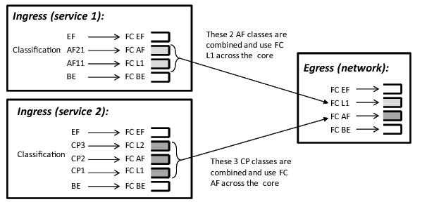
Figure 4 shows the ingress service 1 using forwarding classes AF and L1 that are overridden to L1 for the network egress, while it also shows ingress service 2 using forwarding classes L1, AF, and L2 that are overridden to AF for the network egress.
 
Service Egress QoS Policies
Service egress queues are implemented at the transition from the service core network to the service access network. The advantages of per-service queuing before transmission into the access network are:
The subrate capabilities and per-service scheduling control are required to make multiple services per physical port possible. Without egress shaping, it is impossible to support more than one service per port. There is no way to prevent service traffic from bursting to the available port bandwidth and starving other services.
For accounting purposes, per-service statistics can be logged. When statistics from service ingress queues are compared with service egress queues, the ability to conform to per-service QoS requirements within the service core can be measured. The service core statistics are a major asset to core provisioning tools.
Service egress QoS policies define egress queues and map forwarding class flows to queues. In the simplest service egress QoS policy, all forwarding classes are treated like a single flow and mapped to a single queue. To define a basic egress QoS policy, the following are required:
Optional service egress QoS policy elements include:
Each queue in a policy is associated with one of the forwarding classes. Each queue can have its individual queue parameters allowing individual rate shaping of the forwarding class(es) mapped to the queue.
More complex service queuing models are supported in the router where each forwarding class is associated with a dedicated queue.
The forwarding class determination per service egress packet is determined at ingress. If the packet ingressed the service on the same router, the service ingress classification rules determine the forwarding class of the packet. If the packet is received, the forwarding class is marked in the tunnel transport encapsulation.
Service egress QoS policy ID 1 is reserved as the default service egress policy. The default policy cannot be deleted or changed. The default access egress policy is applied to all SAPs service egress policy explicitly assigned. The characteristics of the default policy are listed in the following table.
 
 
Named Pool Policies
The named buffer pool feature allows for the creation of named buffer pools at the MDA and port level. Named pools allow for a customized buffer allocation mode for ingress and egress queues that goes beyond the default pool behavior.
Named pools are defined within a named pool policy. The policy contains a q1-pools context which is used to define port allocation weights and named pools for buffer pools on Q1 based IOMs (all IOMs that are currently supported). The policy may be applied at either the port or MDA level at which time the pools defined within the policy are created on the port or MDA. When the policy is applied at the MDA level, MDA named pools are created. MDA named pools will typically be used when either a pool cannot be created per port or when the buffering needs of queues mapped to the pool are not affected by sharing the pool with queues from other ports. MDA named pools allow buffers to be efficiently shared between queues on different ports mapped to the same pool. However, MDA named pools do present the possibility that very active queues on one port could deplete buffers in the pool offering the possibility that queues on other ports experiencing buffer starvation. Port named pools are created when the policy is applied at the port level and allow for a more surgical application of the buffer space allocated for a physical port. MDA pool names do not need to be unique. If a name overlaps exists, the port pool will be used. The same pool name may be created on multiple ports on the same MDA.
The named pool policy is applied at the MDA ingress and egress level and at the ingress and egress port level. Each MDA within the system is associated with a forwarding plane traffic manager that has support for a maximum of 57 buffer pools. The following circumstances affect the number of named pools that can be created per MDA (these circumstances may be different between ingress and egress for the MDA):
If the named pool policy is applied to an MDA or port that cannot create every pool defined in the policy, the policy application attempt will fail. Any pre-existing named pool policy on the MDA or port will not be affected by the failed named pool policy association attempt.
When buffer pools are being created or deleted, individual queues may need to be moved to or from the default pools. When a queue is being moved, the traffic destined to the queue is first moved temporarily to a ‘fail-over’ queue. Then the queue is allowed to drain. Once the queue is drained, the statistics for the queue are copied. The queue is then returned to the free queue list. A new queue is then created associated with the appropriate buffer pool, the saved stats are loaded to the queue and then the traffic is moved from the fail-over queue to the new queue. While the traffic is being moved between the old queue to the fail-over queue and then to the new queue, some out of order forwarding may be experienced. Also, any traffic forwarded through the fail-over queue will not be accounted for in billing or accounting statistics. A similar action is performed for queues that have the associated pool name added, changed or removed. Please note this only applies to where fail-over queues are currently supported.
The first step in allowing named pools to be created for an MDA is to enable ‘named-pool-mode’ at the IOM level (config card slot-number named-pool-mode). Named pool mode may be enabled and disabled at anytime. When MDAs are currently provisioned on the IOM, the IOM is reset to allow all existing pools to be deleted and the new default, named MDA and named port pools to be created and sized. If MDAs are not currently provisioned (as when the system is booting up), the IOM is not reset. When named pool mode is enabled, the system changes the way that default pools are created. The system no longer creates default pools per port, instead, a set of per forwarding plane level pools are created that are used by all queues that are not explicitly mapped to a named pool.
After the IOM has been placed into named pool mode, a named pool policy must be associated with the ingress and egress contexts of the MDA or individual ports on the MDA for named pools to be created. There are no named pools that exist by default.
Each time the default pool reserve, aggregate MDA pool limit or individual pool sizes is changed, buffer pool allocation must be re-evaluated.
Pools may be deleted from the named pool policy at anytime. Queues associated with removed or non-existent pools are mapped to one of the default pools based on whether the queue is access or ingress. The queue is flagged as ‘pool-orphaned’ until either the pool comes into existence, or the pool name association is changed on the pool.
An ingress or egress port managed buffer space is derived from the port’s active bandwidth. Based on this bandwidth value compared to the other port’s bandwidth value, the available buffer space is given to each port to manage. It may be desirable to artificially increase or decrease this bandwidth value to compensate for how many buffers are actually needed on each port. If one port has very few queues associated with it and another has many queues associated, the commands in the port’s “modify-buffer-allocation-rate” CLI context may be used to move one port’s bandwidth up, and another port’s bandwidth down. As provisioning levels change between ports, the rate modification commands may be used to adapt the buffer allocations per port.
Buffer allocation rate modification is supported for both standard and named pool mode buffer allocation methods.
The system allocates buffers based on the following criteria:
Slope Policies
For network ingress, a buffer pool is created for the MDA and is used for all network ingress queues for ports on the MDA.
Slope policies define the RED slope characteristics as a percentage of pool size for the pool on which the policy is applied.
Default buffer pools exist (logically) at the port and MDA levels. Each physical port has two pools objects associated:
By default, each pool is associated with slope-policy default.
Access, and network pools (in network mode) and access uplink pools (in access uplink mode) are created at the port level; creation is dependent on the physical port mode (network, access) or the mode of provisioned channel paths.
Node-level pools are used by ingress network queues and bundle access queues. A single ingress network pool is created at the node-level for ingress network queues.
An ingress and egress access pool is created at the MDA level for all bundle access queues.
 
RED Slopes
 
Operation and Configuration
Each buffer pool supports a high-priority RED slope, a non-TCP RED slope, and a low-priority RED slope. The high-priority RED slope manages access to the shared portion of the buffer pool for high-priority or in-profile packets. The low-priority RED slope manages access to the shared portion of the buffer pool for low-priority or out-of-profile packets.
For access buffer pools, the percentage of the buffers that are to be reserved for CBS buffers is configured by the user software (cannot be changed by user). This setting indirectly assigns the amount of shared buffers on the pool. This is an important function that controls the ultimate average and total shared buffer utilization value calculation used for RED slope operation. The CBS setting can be used to dynamically maintain the buffer space on which the RED slopes operate.
For network buffer pools, the CBS setting does not exist; instead, the configured CBS values for each network forwarding class queue inversely defines the shared buffer size. If the total CBS for each queue equals or exceeds 100% of the buffer pool size, the shared buffer size is equal to 0 (zero) and a queue cannot exceed its CBS.
When a queue depth exceeds the queue’s CBS, packets received on that queue must contend with other queues exceeding their CBS for shared buffers. To resolve this contention, the buffer pool uses two RED slopes to determine buffer availability on a packet by packet basis. A packet that was either classified as high priority or considered in-profile is handled by the high-priority RED slope. This slope should be configured with RED parameters that prioritize buffer availability over packets associated with the low-priority RED slope. Packets that had been classified as low priority or out-of-profile are handled by this low-priority RED slope.
The following is a simplified overview of how a RED slope determines shared buffer availability on a packet basis:
1.
2.
3.
4.
5.
6.
7.
8.
9.
10.
Figure 5: RED Slope Characteristics
A RED slope itself is a graph with an X (horizontal) and Y (vertical) axis. The X-axis plots the percentage of shared buffer average utilization, going from 0 to 100 percent. The Y-axis plots the probability of packet discard marked as 0 to 1. The actual slope can be defined as four sections in (X, Y) points (Figure 5):
1.
2.
3.
4.
Plotting any value of shared buffer average utilization will result in a value for packet discard probability from 0 to 1. Changing the values for start-avg, max-avg and max-prob allows the adaptation of the RED slope to the needs of the access or network queues using the shared portion of the buffer pool, including disabling the RED slope.
 
Tuning the Shared Buffer Utilization Calculation
The router allows tuning the calculation of the Shared Buffer Average Utilization (SBAU) after assigning buffers for a packet entering a queue as used by the RED slopes to calculate a packet’s drop probability. The router implements a time average factor (TAF) parameter in the buffer policy which determines the contribution of the historical shared buffer utilization and the instantaneous Shared Buffer Utilization (SBU) in calculating the SBAU. The TAF defines a weighting exponent used to determine the portion of the shared buffer instantaneous utilization and the previous shared buffer average utilization used to calculate the new shared buffer average utilization. To derive the new shared buffer average utilization, the buffer pool takes a portion of the previous shared buffer average and adds it to the inverse portion of the instantaneous shared buffer utilization (SBU). The formula used to calculated the average shared buffer utilization is:
where:
SBAUn = Shared buffer average utilization for event n
SBAUn-1 = Shared buffer average utilization for event (n-1)
SBU = The instantaneous shared buffer utilization
TAF = The time average factor
Table 17 shows the effect the allowed values of TAF have on the relative weighting of the instantaneous SBU and the previous SBAU (SBAUn-1) has on the calculating the current SBAU (SBAUn).
 
2TAF
20
21
22
23
24
25
26
27
28
29
210
211
212
213
214
215
The value specified for the TAF affects the speed at which the shared buffer average utilization tracks the instantaneous shared buffer utilization. A low value weights the new shared buffer average utilization calculation more to the shared buffer instantaneous utilization. When TAF is zero, the shared buffer average utilization is equal to the instantaneous shared buffer utilization. A high value weights the new shared buffer average utilization calculation more to the previous shared buffer average utilization value. The TAF value applies to all high and low priority RED slopes for ingress and egress buffer pools controlled by the buffer policy.
 
Slope Policy Parameters
The elements required to define a slope policy are:
Unlike access QoS policies where there are distinct policies for ingress and egress, slope policy is defined with generic parameters so that it is not inherently an ingress or an egress policy. A slope policy defines ingress properties when it is associated with an access port buffer pool on ingress and egress properties when it is associated with an access buffer pool on egress.
Each access port buffer pool can be associated with one slope policy ID on ingress and one slope policy ID on egress. The slope policy IDs on ingress and egress can be set independently.
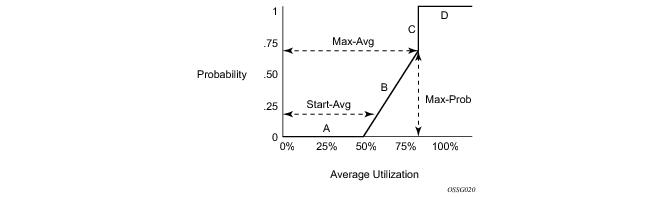
Slope policy ID default is reserved for the default slope policy. The default policy cannot be deleted or changed. The default slope policy is implicitly applied to all access buffer pools which do not have another slope policy explicitly assigned.
Table 18 lists the default values for the default slope policy.


Scheduler Policies
A scheduler policy defines the hierarchy and all operating parameters for the member schedulers. A scheduler policy must be defined in the QoS context before a group of virtual schedulers can be used. Although configured in a scheduler policy, the individual schedulers are actually created when the policy is applied to a site, such as a SAP or interface.
Scheduler objects define bandwidth controls that limit each child (other schedulers and queues) associated with the scheduler. The scheduler object can also define a child association with a parent scheduler of its own.
A scheduler is used to define a bandwidth aggregation point within the hierarchy of virtual schedulers. The scheduler’s rate defines the maximum bandwidth that the scheduler can consume. It is assumed that each scheduler created will have queues or other schedulers defined as child associations. The scheduler can also be a child (take bandwidth from) a scheduler in a higher tier, except for schedulers created in Tier 1.
A parent parameter can be defined to specify a scheduler further up in the scheduler policy hierarchy. Only schedulers in Tiers 2 and 3 can have parental association. Tier 1 schedulers cannot have a parental association. When multiple schedulers and/or queues share a child status with the scheduler on the parent, the weight or strict parameters define how this scheduler contends with the other children for the parent’s bandwidth. The parent scheduler can be removed or changed at anytime and is immediately reflected on the schedulers actually created by association of this scheduler policy.
When a parent scheduler is defined without specifying level, weight, or CIR parameters, the default bandwidth access method is weight with a value of 1.
If any orphaned queues (queues specifying a scheduler name that does not exist) exist on the ingress SAP and the policy application creates the required scheduler, the status on the queue becomes non-orphaned at this time.
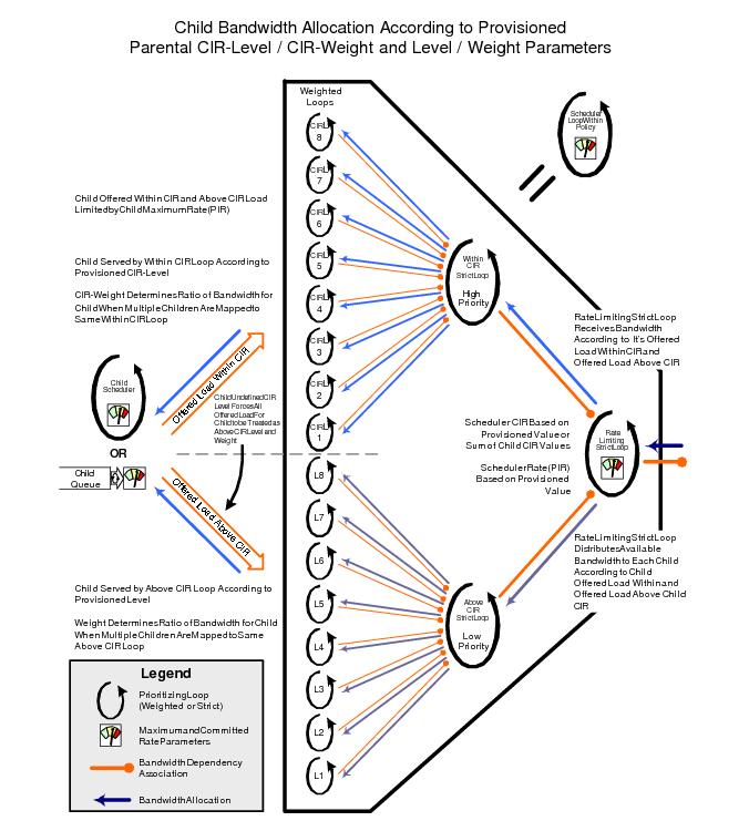
Figure 6 depicts how child queues and schedulers interact with their parent scheduler to receive bandwidth. The scheduler distributes bandwidth to the children by first using each child’s CIR according to the CIR-level parameter (CIR L8 through CIR L1 weighted loops). The weighting at each CIR-Level loop is defined by the CIR weight parameter for each child. The scheduler then distributes any remaining bandwidth to the children up to each child’s rate parameter according to the Level parameter (L8 through L1 weighted loops). The weighting at each level loop is defined by the weight parameter for each child.
.
Figure 6: Virtual Scheduler Internal Bandwidth Allocation
Virtual Hierarchical Scheduling
Virtual hierarchical scheduling is a method that defines a bounded operation for a group of queues. One or more queues are mapped to a given scheduler with strict and weighted metrics controlling access to the scheduler. The scheduler has an optional prescribed maximum operating rate that limits the aggregate rate of the child queues. This scheduler may then feed into another virtual scheduler in a higher tier. The creation of a hierarchy of schedulers and the association of queues to the hierarchy allows for a hierarchical Service Level Agreement (SLA) to be enforced.
Scheduler policies in the routers determine the order queues are serviced. All ingress and egress queues operate within the context of a scheduler. Multiple queues share the same scheduler. Schedulers control the data transfer between the following queues and destinations:
There are two types of scheduler policies:
Schedulers and scheduler policies control the data transfer between queues, switch fabric destinations and egress ports/interfaces. The type of scheduling available for the various scheduling points within the system are summarized in Table 20.
 
Tiers
In single tier scheduling, queues are scheduled based on the forwarding class of the queue and the operational state of the queue relative to the queue’s CIR and PIR. Queues operating within their CIR values are serviced before queues operating above their CIR values with “high-priority” forwarding class queues given preference over “low-priority” forwarding class queues. In single tier scheduling, all queues are treated as if they are at the same “level” and the queue’s parameters and operational state directly dictate the queue’s scheduling. Single tier scheduling is the system default scheduling policy for all the queues and destinations listed above and has no configurable parameters.
Hierarchical scheduler policies are an alternate way to schedule queues that can be used on service ingress and service egress queues. Hierarchical scheduler policies allow the creation of a hierarchy of schedulers where queues and/or other schedulers are scheduled by superior schedulers.
To illustrate the difference between single tier scheduling and hierarchical scheduling policies, consider a simple case where, on service ingress, three queues are created for gold, silver and bronze service and are configured as follows:
In the router, the CIR is used for policing of traffic (in-profile or out-of-profile), and the PIR is the rate at which traffic is shaped out of the queue. In single tier scheduling, each queue can burst up to its defined PIR, which means up to 150 Mbps (10 Mbps + 40 Mbps + 100 Mbps) can enter the service.
In a simple example of a hierarchical scheduling policy, a superior (or parent) scheduler can be created for the gold, silver and bronze queues which limits the overall rate for all queues to 100 Mbps. In this hierarchical scheduling policy, the customer can send in any combination of gold, silver and bronze traffic conforming to the defined PIR values and not to exceed 100 Mbps.
 
Single Tier Scheduling
Single-tier scheduling is the default method of scheduling queues in the router. Queues are scheduled with single-tier scheduling if no explicit hierarchical scheduler policy is defined or applied. There are no configurable parameters for single-tier scheduling.
In single tier scheduling, queues are scheduled based on the Forwarding Class of the queue and the operational state of the queue relative to the queue’s Committed Information Rate (CIR) and Peak Information Rate (PIR). Queue’s operating within their CIR values are serviced before queue’s operating above their CIR values with “high-priority” forwarding class queues given preference over “low-priority” forwarding class queues. In Single Tier Scheduling, all queues are treated as if they are at the same “level” and the queue’s parameters and operational state directly dictate the queue’s scheduling.
A pair of schedulers, a high-priority and low-priority scheduler, transmits to a single destination switch fabric port, access port, or network interface. Table 21 below lists how the forwarding class queues are mapped to the high and low scheduler:
 
Note, that by using the default QoS profile, all ingress traffic is treated as best effort (be) (mapped to FC be and to low priority scheduler). For an egress SAP using the default QoS profile, all egress traffic will use the same queue.
While competing for bandwidth to the destination, each scheduler determines which queue will be serviced next. During congestion (packets existing on multiple queues), queues are serviced in the following order:
1.
2.
3.
Queues associated with a single scheduler are serviced in a round robin method. If a queue reaches the configured PIR, the scheduler will not serve the queue until the transmission rate drops below the PIR.
The router QoS features are flexible and allow modifications to the forwarding class characteristics and the CIR and PIR queue parameters. The only fundamental QoS mechanisms enforced within the hardware are the association of the forwarding classes with the high priority or low priority scheduler and the scheduling algorithm. Other parameters can be modified to configure the appropriate QoS behavior.
 
Hierarchical Scheduler Policies
Hierarchical scheduler policies are an alternate way of scheduling queues which can be used on service ingress and service egress queues. Hierarchical scheduler policies allow the creation of a hierarchy of schedulers where queues and/or other schedulers are scheduled by superior schedulers.
The use of the hierarchical scheduler policies is often referred to as hierarchical QoS or H-QoS on the SR OS.
 
Hierarchical Virtual Schedulers
Virtual schedulers are created within the context of a hierarchical scheduler policy. A hierarchical scheduler policy defines the hierarchy and parameters for each scheduler. A scheduler is defined in the context of a tier (Tier 1, Tier 2, Tier 3). The tier level determines the scheduler’s position within the hierarchy. Three tiers of virtual schedulers are supported (Figure 7). Tier 1 schedulers (also called root schedulers) are defined without a parent scheduler. It is not necessary for Tier 1 schedulers to obtain bandwidth from a higher tier scheduler. A scheduler can enforce a maximum rate of operation for all child queues and associated schedulers.
Figure 7: Hierarchical Scheduler and Queue Association
 
Scheduler Policies Applied to Applications
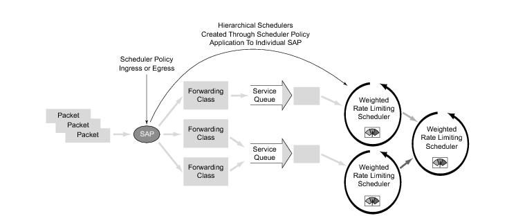
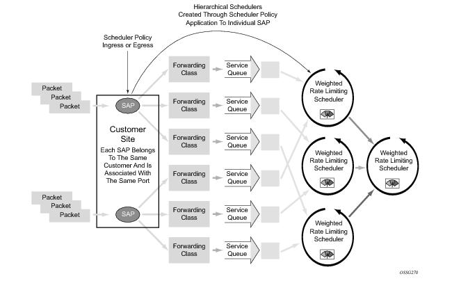
A scheduler policy can be applied either on a SAP (Figure 8) or on a multi-service customer site (a group of SAPs with common origination/termination point) (Figure 9). Whenever a scheduler policy is applied, the individual schedulers comprising the policy are created on the object. When the object is an individual SAP, only queues created on that SAP can use the schedulers created by the policy association. When the object is a multi-service customer site, the schedulers are available to any SAPs associated with the site (also see Scheduler Policies Applied to SAPs).
Refer to the Subscriber Services Overview section of the Services Guide for information about subscriber services, service entities, configuration, and implementation.
Figure 8: Scheduler Policy on SAP and Scheduler Hierarchy Creation
Figure 9: Scheduler Policy on Customer Site and Scheduler Hierarchy Creation
Queues become associated with schedulers when the parent scheduler name is defined within the queue definition in the SAP ingress policy. The scheduler is used to provide bandwidth to the queue relative to the operating constraints imposed by the scheduler hierarchy.
 
Scheduler Policies Applied to SAPs
A scheduler policy can be applied to create egress schedulers used by SAP queues. The schedulers comprising the policy are created at the time the scheduler policy is applied to the SAP. If any orphaned queues exist (queues specifying a scheduler name that does not exist) on the egress SAP and the policy application creates the required scheduler, the status on the queue will become non-orphaned.
Queues are associated with the configured schedulers by specifying the parent scheduler defined within the queue definition from the SAP egress policy. The scheduler is used to provide bandwidth to the queue relative to the operating constraints imposed by the scheduler hierarchy.
Customer Service Level Agreement (SLA)
The router implementation of hierarchical QoS allows a common set of virtual schedulers to govern bandwidth over a set of customer services that is considered to be from the same site. Different service types purchased from a single customer can be aggregately accounted and billed based on a single Service Level Agreement.
By configuring multi-service sites within a customer context, the customer site can be used as an anchor point to create an ingress and egress virtual scheduler hierarchy.
Once a site is created, it must be assigned to the chassis slot or a port (except in the 7750 SR-1 model, the slot is automatically set to 1). This allows the system to allocate the resources necessary to create the virtual schedulers defined in the ingress and egress scheduler policies. This also acts as verification that each SAP assigned to the site exists within the context of the customer ID and that the SAP was created on the correct slot, port, or channel. The specified slot or port must already be pre-provisioned (configured) on the system.
When scheduler policies are defined for ingress and egress, the scheduler names contained in each policy are created according to the parameters defined in the policy. Multi-service customer sites are configured only to create a virtual scheduler hierarchy and make it available to queues on multiple SAPs.
 
Scheduler Policies Applied to Multi-Service Sites
Only an existing scheduler policy and scheduler policy names can be applied to create the ingress or egress schedulers used by SAP queues associated with a customer’s multi-service site. The schedulers defined in the scheduler policy can only be created after the customer site has been appropriately assigned to a chassis port, channel, or slot. Once a multi-service customer site is created, SAPs owned by the customer must be explicitly included in the site. The SAP must be owned by the customer the site was created within and the site assignment parameter must include the physical locale of the SAP.
 
Forwarding Classes
Routers support multiple forwarding classes and class-based queuing, so the concept of forwarding classes is common to all of the QoS policies.
Each forwarding class (also called Class of Service (CoS)) is important only in relation to the other forwarding classes. A forwarding class provides network elements a method to weigh the relative importance of one packet over another in a different forwarding class.
Queues are created for a specific forwarding class to determine the manner in which the queue output is scheduled into the switch fabric. The forwarding class of the packet, along with the in-profile or out-of-profile state, determines how the packet is queued and handled (the per hop behavior (PHB)) at each hop along its path to a destination egress point. Routers support eight (8) forwarding classes (Table 22).
 
Note that Table 22 presents the default definitions for the forwarding classes. The forwarding class behavior, in terms of ingress marking interpretation and egress marking, can be changed by a Network QoS Policies. All forwarding class queues support the concept of in-profile and out-of-profile.
The forwarding classes can be classified into three class types:
 
High-Priority Classes
The high-priority forwarding classes are Network Control (nc), Expedited (ef), High 1 (h1), and High 2 (h2). High-priority forwarding classes are always serviced at congestion points over other forwarding classes; this behavior is determined by the router queue scheduling algorithm (Virtual Hierarchical Scheduling).
With a strict PHB at each network hop, service latency is mainly affected by the amount of high-priority traffic at each hop. These classes are intended to be used for network control traffic or for delay or jitter-sensitive services.
If the service core network is over-subscribed, a mechanism to traffic engineer a path through the core network and reserve bandwidth must be used to apply strict control over the delay and bandwidth requirements of high-priority traffic. In the router, RSVP-TE can be used to create a path defined by an MPLS LSP through the core. Premium services are then mapped to the LSP with care exercised to not oversubscribe the reserved bandwidth.
If the core network has sufficient bandwidth, it is possible to effectively support the delay and jitter characteristics of high-priority traffic without utilizing traffic engineered paths, as long as the core treats high-priority traffic with the proper PHB.
 
Assured Classes
The assured forwarding classes are Assured (af) and Low 1 (l1). Assured forwarding classes provide services with a committed rate and a peak rate much like Frame Relay. Packets transmitted through the queue at or below the committed transmission rate are marked in-profile. If the core service network has sufficient bandwidth along the path for the assured traffic, all aggregate in-profile service packets will reach the service destination. Packets transmitted out the service queue that are above the committed rate will be marked out-of-profile. When an assured out-of-profile service packet is received at a congestion point in the network, it will be discarded before in-profile assured service packets.
Multiple assured classes are supported with relative weighting between them. In DiffServ, the code points for the various Assured classes are AF4, AF3, AF2 and AF1. Typically, AF4 has the highest weight of the four and AF1 the lowest. The Assured and Low 1 classes are differentiated based on the default DSCP mappings. Note that all DSCP and EXP mappings can be modified by the user.
 
Best-Effort Classes
The best-effort classes are Low 2 (l2) and Best-Effort (be). The best-effort forwarding classes have no delivery guarantees. All packets within this class are treated, at best, like out-of-profile assured service packets.
 
Shared Queues
Shared-queue QoS policies can be implemented to facilitate queue consumption on an MDA. It is especially useful when VPLS, IES, and VPRN services are scaled on one MDA. Instead of allocating multiple hardware queues for each unicast queue defined in a SAP ingress QoS policy, SAPs with the shared-queuing feature enabled only allocate one hardware queue for each SAP ingress QoS policy unicast queue.
However, as a tradeoff, the total amount of traffic throughput at ingress of the node is reduced because any ingress packet serviced by a shared-queuing SAP is recirculated for further processing. When the node is only used for access SAPs, 5 Gbps ingress traffic is the maximum that can be processed without seeing packet drops at the MDA ingress. The reason for this is that any ingress packet serviced by a shared-queuing SAP is processed twice in Flexible Fast Path which greatly reduces bandwidth.
Shared-queuing can add latency. Network planners should consider these restrictions while trying to scale services on one MDA.
 
ATM Traffic Descriptor Profiles
Traffic descriptors profiles capture the cell arrival pattern for resource allocation. Source traffic descriptors for an ATM connection include at least one of the following:
QoS Traffic descriptor profiles are applied on IES, VPRN, VPLS, and VLL SAPs.
QoS Policy Entities
Services are configured with default QoS policies. Additional policies must be explicitly created and associated. There is one default service ingress QoS policy, one default service egress QoS policy, and one default network QoS policy. Only one ingress QoS policy and one egress QoS policy can be applied to a SAP or network port.
When you create a new QoS policy, default values are provided for most parameters with the exception of the policy ID and queue ID values, descriptions, and the default action queue assignment. Each policy has a scope, default action, a description, and at least one queue. The queue is associated with a forwarding class.
QoS policies can be applied to the following service types:
QoS policies can be applied to the following entities:
Default QoS policies maps all traffic with equal priority and allow an equal chance of transmission (Best Effort (be) forwarding class) and an equal chance of being dropped during periods of congestion. QoS prioritizes traffic according to the forwarding class and uses congestion management to control access ingress, access egress, and network traffic with queuing according to priority
 
Frequently Used QoS Terms
The following terms are used in router Hierarchical QoS to describe the operation and maintenance of a virtual scheduler hierarchy and are presented for reference purposes.
 
Above CIR Distribution
‘Above CIR’ distribution is the second phase of bandwidth allocation between a parent scheduler and its child queues and child schedulers. The bandwidth that is available to the parent scheduler after the ‘within CIR’ distribution is distributed among the child members using each child’s level (to define strict priority for the above CIR distribution), Weight (the ratio at a given level with several children) and the child’s rate value. A rate value equal to the child’s CIR value results in a child not receiving any bandwidth during the ‘above CIR’ distribution phase.
Available Bandwidth
Available bandwidth is the bandwidth usable by a parent scheduler to distribute to its child queues and schedulers. The available bandwidth is limited by the parent’s schedulers association with its parent scheduler. If the parent scheduler has a parent of its own and the parent schedulers defined rate value, then available bandwidth is distributed to the child queues and schedulers using a ‘within CIR’ distribution phase and an ‘above CIR’ distribution phase. Distribution in each phase is based on a combination of the strict priority of each child and the relative weight of the child at that priority level. Separate priority and weight controls are supported per child for each phase.
CBS
The Committed Burst Size (CBS) specifies the relative amount of reserved buffers for a specific ingress network MDA forwarding class queue or egress network port forwarding class queue. The value is entered as a percentage.
CIR
The Committed Information Rate (CIR) defines the amount of bandwidth committed to the scheduler or queue.
The CIR rate for ingress queues controls the in-profile and out-of-profile policing and ultimately egress in-profile and out-of-profile marking. Queue CIR rates also define the hardware fairness threshold at which the queue is no longer prioritized over other queues.
A child’s (queue or scheduler) CIR is used with the CIR level parameter to determine the child’s committed bandwidth from the parent scheduler. When multiple children are at the same strict CIR level, the CIR weight further determines the bandwidth distribution at that level.
CIR Level
The CIR level parameter defines the strict level at which bandwidth is allocated to the child queue or scheduler during the within CIR distribution phase of bandwidth allocation. All committed bandwidth (determined by the CIR defined for the child) is allocated before any child receives non-committed bandwidth. Bandwidth is allocated to children at the higher CIR levels before children at a lower level. A child CIR value of zero or an undefined CIR level results in bandwidth allocation to the child only after all other children receive their provisioned CIR bandwidth. When multiple children share a CIR level, the CIR weight parameter further defines bandwidth allocation according to the child’s weight ratio.
CIR Weight
The CIR weight parameter defines the weight within the CIR level given to a child queue or scheduler. When multiple children share the same CIR level on a parent scheduler, the ratio of bandwidth given to an individual child is dependent on the ratio of the weights of the active children. A child is considered active when a portion of the offered load is within the child’s defined CIR rate. The ratio is calculated by first adding the CIR weights of all active children and then dividing each child’s CIR weight by the sum. If a child’s CIR level parameter is not defined, that child is not included in the within CIR distribution and the CIR weight parameter is ignored. A CIR weight of zero forces the child to receive bandwidth only after all other children at that level have received their ‘within CIR’ bandwidth. When several children share a CIR weight of zero, all are treated equally.
Child
Child is a logical state of a queue or scheduler that has been configured with a valid parent scheduler association. The child/parent association is used to build the hierarchy among the queues and schedulers.
Level
The level parameter defines the strict priority level for a child queue or scheduler with regards to bandwidth allocation during the above CIR distribution phase on the child’s parent scheduler. This allocation of bandwidth is done after the ‘within CIR’ distribution is finished. All child queues and schedulers receive the remaining bandwidth according to the strict priority level in which they are defined with higher levels receiving bandwidth first and lower levels receiving bandwidth if available.
MBS
The Maximum Burst Size (MBS) command specifies the relative amount of the buffer pool space for the maximum buffers for a specific ingress network MDA forwarding class queue or egress network port forwarding class queue. The value is entered as a percentage.
MCR
The Minimum Cell Rate (MCR).
Offered Load
Offered load is evaluated per child in the scheduler hierarchy. The offered load is the amount of bandwidth a child queue or scheduler can use to accommodate the data passing through the child. It is separated into two portions; within CIR and above CIR. Within CIR offered load is the portion of bandwidth required to meet the child’s CIR value. It can be less than the CIR value but never greater. If the forwarding requirement for the child is greater than the CIR value, the remaining is considered to be the above CIR offered load. The sum of the within CIR and above CIR offered load cannot be greater than the maximum rate defined for the child.
Orphan
When a child queue is configured with a parent scheduler specified but the parent scheduler does not exist on the object the queue is created on, the state is considered orphaned.
An orphaned state is not the same condition as when a queue is not defined with a parent association. Orphan states are cleared when the parent scheduler becomes available on the object. This can occur when a scheduler policy containing the parent scheduler name is applied to the object that the queue exists on or when the scheduler name is added to the scheduler policy already applied to the object that the queue exists on.
Parent
A scheduler becomes a parent when a queue or scheduler defines it as its parent. A queue or scheduler can be a child of only one scheduler. When defining a parent association on a child scheduler, the parent scheduler must already exist in the same scheduler policy and on a scheduler tier higher (numerically lower) then the child scheduler. Parent associations for queues are only checked once, when an instance of the queue is created on a SAP.
Queue
A queue is where packets that will be forwarded are buffered before scheduling. Packets are not actually forwarded through the schedulers; they are forwarded from the queues directly to ingress or egress interfaces. The association between the queue and the virtual schedulers is intended to accomplish bandwidth allocation to the queue. Because the offered load is derived from queue utilization, bandwidth allocation is dependent on the queue distribution among the scheduler hierarchy. Queues can be tied to only one scheduler within the hierarchy.
Rate
The rate defines the maximum bandwidth that will be made available to the scheduler or queue. The rate is defined in kilobits per second (Kbps).
Root (Scheduler)
A scheduler that has no parent scheduler association (is not a child of another scheduler) is considered to be a root scheduler. With no parent scheduler, bandwidth utilized by a root scheduler is dependent on offered load of child members, the maximum rate defined for the scheduler and total overall available bandwidth. Any scheduler can be a root scheduler. Since parent associations are not allowed in Tier 1, all schedulers in Tier 1 are considered be a root scheduler.
Scheduler Policy
A scheduler policy represents a particular grouping of virtual schedulers that are defined in specific scheduler tiers. The tiers and internal parent associations between the schedulers establish the hierarchy among the virtual schedulers. A scheduler policy can be applied to either a multi-service site or to a service Service Access Point (SAP). Once the policy is applied to a site or SAP, the schedulers in the policy are instantiated on the object and are available for use by child queues directly or indirectly associated with the object.
Tier
A tier is an organizational configuration used within a scheduler policy to define the place of schedulers created in the policy. Three tiers are supported; Tier 1, Tier 2, and Tier 3. Schedulers defined in Tier 2 can have parental associations with schedulers defined in Tier 1. Schedulers defined in Tier 3 can have parental associations with schedulers defined at Tiers 1 or 2. Queues can have parental associations with schedulers at any tier level.
Virtual Scheduler
A virtual scheduler, defined by a name (text string), is a logical configuration used as a parent to a group of child members that are dependent upon a common parent for bandwidth allocation. The virtual scheduler can also be a child member to another parent virtual scheduler and receive bandwidth from that parent to distribute to its child members.
Weight
The weight parameter defines the weight within the ‘above CIR’ level given to a child queue or scheduler. When several children share the same level on a parent scheduler, the ratio of bandwidth give to an individual child is dependent on the ratio of the weights of the active children. A child is considered active when a portion of the offered load is above the CIR value (also bounded by the child’s maximum bandwidth defined by the child’s rate parameter). The portion of bandwidth given to each child is based on the child’s weight compared to the sum of the weights of all active children at that level. A weight of zero forces the child to receive bandwidth only after all other children at that level have received their ‘above CIR’ bandwidth. When several children share a weight of zero, all are treated equally.
Within CIR Distribution
Within the CIR distribution process is the initial phase of bandwidth allocation between a parent scheduler and its child queues and child schedulers. The bandwidth that is available to the parent scheduler is distributed first among the child members using each child’s CIR level (to define a strict priority for the CIR distribution), CIR weight (the ratio at a given CIR level with several children), and the child’s CIR value. A CIR value of zero or an undefined CIR level causes a child to not receive any bandwidth during the CIR distribution phase. If the parent scheduler has any bandwidth remaining after the ‘within CIR’ distribution phase, it will be distributed using the above CIR distribution phase.
Configuration Notes
The following information describes QoS implementation caveats: