For feedback and comments: |
documentation.feedback@alcatel-lucent.com |
→ Figure 1: Internet Enhanced ServiceNote: Refer to the 7750 SR Triple Play Guide for information about how subscriber group-interfaces function in the Routed Central Office model.This section describes the 7750 SR service features and any special capabilities or considerations as they relate to IES services.
• This section discusses QPPB as it applies to VPRN, IES, and router interfaces. Refer to the Internet Enhanced Service section on and the IP Router Configuration section in the 7x50 OS Router Configuration Guide.Figure 2 shows an example of an ISP that has an agreement with the content provider managing AS300 to provide traffic sourced and terminating within AS300 with differentiated service appropriate to the content being transported. In this example we presume that ASBR1 and ASBR2 mark the DSCP of packets terminating and sourced, respectively, in AS300 so that other nodes within the ISP’s network do not need to rely on QPPB to determine the correct forwarding-class to use for the traffic. Note however, that the DSCP or other COS markings could be left unchanged in the ISP’s network and QPPB used on every node.
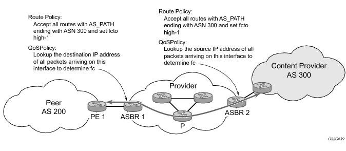
• fc fc-name [priority {low | high}]config>router>policy-optionsbegincommunity gold members 300:100policy-statement qppb_policyentry 10fromprotocol bgpcommunity goldexitaction acceptfc h1 priority highexitexitexitcommitThe fc command is supported with all existing from and to match conditions in a route policy entry and with any action other than reject, it is supported with next-entry, next-policy and accept actions. If a next-entry or next-policy action results in multiple matching entries then the last entry with a QPPB action determines the forwarding class and priority.A route policy that includes the fc command in one or more entries can be used in any import or export policy but the fc command has no effect except in the following types of policies:
• static-route {ip-prefix/prefix-length | ip-prefix netmask} [fc fc-name [priority {low | high}]] next-hop ip-int-name|ip-address
• static-route {ip-prefix/prefix-length | ip-prefix netmask} [fc fc-name [priority {low | high}]] indirect ip-addressThis feature uses a qos keyword to the show>router>route-table command. When this option is specified the output includes an additional line per route entry that displays the forwarding class and priority of the route. If a route has no fc and priority information then the third line is blank. The following CLI shows an example:show router route-table [family] [ip-prefix[/prefix-length]] [longer | exact] [protocol protocol-name] qosA:Dut-A# show router route-table 10.1.5.0/24 qos===============================================================================Route Table (Router: Base)===============================================================================Dest Prefix Type Proto Age PrefNext Hop[Interface Name] MetricQoS-------------------------------------------------------------------------------10.1.5.0/24 Remote BGP 15h32m52s 0PE1_to_PE2 0h1, high-------------------------------------------------------------------------------No. of Routes: 1===============================================================================A:Dut-A#To enable QoS classification of ingress IP packets on an interface based on the QoS information associated with the routes that best match the packets the qos-route-lookup command is necessary in the configuration of the IP interface. The qos-route-lookup command has parameters to indicate whether the QoS result is based on lookup of the source or destination IP address in every packet. There are separate qos-route-lookup commands for the IPv4 and IPv6 packets on an interface, which allows QPPB to enabled for IPv4 only, IPv6 only, or both IPv4 and IPv6. Note however, current QPPB based on a source IP address is not supported for IPv6 packets nor is it supported for ingress subscriber management traffic on a group interface.Note: QPPB based on a source IP address is not supported for ingress subscriber management traffic on a group interface.When ECMP is enabled some routes may have multiple equal-cost next-hops in the forwarding table. When an IP packet matches such a route the next-hop selection is typically based on a hash algorithm that tries to load balance traffic across all the next-hops while keeping all packets of a given flow on the same path. The QPPB configuration model described in Associating an FC and Priority with a Route allows different QoS information to be associated with the different ECMP next-hops of a route. The forwarding-class and priority of a packet matching an ECMP route is based on the particular next-hop used to forward the packet.When BGP fast reroute [1] is enabled some BGP routes may have a backup next-hop in the forwarding table in addition to the one or more primary next-hops representing the equal-cost best paths allowed by the ECMP/multipath configuration. When an IP packet matches such a route a reachable primary next-hop is selected (based on the hash result) but if all the primary next-hops are unreachable then the backup next-hop is used. The QPPB configuration model described in Associating an FC and Priority with a Route allows the forwarding-class and priority associated with the backup path to be different from the QoS characteristics of the equal-cost best paths. The forwarding class and priority of a packet forwarded on the backup path is based on the fc and priority of the backup route.Source-address based QPPB is not supported on any SAP or spoke SDP interface of a VPRN configured with the grt-lookup command.When QPPB is enabled on a SAP IP interface the forwarding class of a packet may change from fc1, the original fc determined by the SAP ingress QoS policy to fc2, the new fc determined by QPPB. In the ingress datapath SAP ingress QoS policies are applied in the first P chip and route lookup/QPPB occurs in the second P chip. This has the implications listed below:
• The profile state of a SAP ingress packet that matches a QPPB route depends on the configuration of fc2 only. If the de-1-out-profile flag is enabled in fc2 and fc2 is not mapped to a priority mode queue then the packet will be marked out of profile if its DE bit = 1. If the profile state of fc2 is explicitly configured (in or out) and fc2 is not mapped to a priority mode queue then the packet is assigned this profile state. In both cases there is no consideration of whether or not fc1 was mapped to a priority mode queue.
• The priority of a SAP ingress packet that matches a QPPB route depends on several factors. If the de-1-out-profile flag is enabled in fc2 and the DE bit is set in the packet then priority will be low regardless of the QPPB priority or fc2 mapping to profile mode queue, priority mode queue or policer. If fc2 is associated with a profile mode queue then the packet priority will be based on the explicitly configured profile state of fc2 (in profile = high, out profile = low, undefined = high), regardless of the QPPB priority or fc1 configuration. If fc2 is associated with a priority mode queue or policer then the packet priority will be based on QPPB (unless DE=1), but if no priority information is associated with the route then the packet priority will be based on the configuration of fc1 (if fc1 mapped to a priority mode queue then it is based on DSCP/IP prec/802.1p and if fc1 mapped to a profile mode queue then it is based on the profile state of fc1).Table 2 summarizes these interactions.
1.
2. Associate the IP interface to the oper-group using the monitor-group command.The following configuration shows the oper-group g1, the VPLS SAP that is mapped to it and the IP interfaces in IES service 2001 monitoring the oper-group g1. This is example uses an R-VPLS context. The VPLS instance includes the allow-ip-int-binding and the service-name v1. The IES interface links to the VPLS using the vpls v1 option. All commands are under the configuration service hierarchy.oper-group g1 createvpls 1 customer 1 createallow-ip-int-bindingstpshutdownexitservice-name "v1"sap 1/1/1:2001 createoper-group g1eth-cfmmep domain 1 association 1 direction downccm-enableno shutdownexitexitsap 1/1/2:2001 createexitsap 1/1/3:2001 createexitno shutdownies 2001 customer 1 createinterface "i2001" createaddress 21.1.1.1/24monitor-oper-group "g1"vpls "v1"exitno shutdownexitSubscriber interfaces are composed of a combination of two key technologies, subscriber interfaces and group interfaces. While the subscriber interface defines the subscriber subnets, the group interfaces are responsible for aggregating the SAPs.A new command, host-accounting, is introduced under accounting-policy, which allows configurable behavior.When no host-accounting is configured, accounting behavior is as follows:When host-accounting is configured, additional RADIUS accounting messages are created for host activity in addition to messages for common queue accounting. The behavior is as follows:Note that Interim-Acct records are not sent for hosts, only the start- and stop-accounting messages.
Table 3: RADIUS Accounting Table
• Figure 3 illustrates the architecture of an aggregation network that uses pseudowire SAPs.pw-port 1 createexitpw-port 2 createexitservicecustomer 1 createmulti-service-site “abc” createassignment port pw-1egresspolicer-control-policy “abc”exitexitdescription “Default customer”exitsdp 1 mpls createfar-end 10.1.1.2ldppath-mtu 1514keep-aliveshutdownexitbindingport lag-1pw-port 1 vc-id 1 createno shutdownexitpw-port 2 vc-id 2 createno shutdownexitexitno shutdownexities 1 customer 1 createinterface “ies if” createaddress 30.1.1.1/24mac 00:00:00:00:00:ffstatic-arp 30.1.1.2 00:00:00:00:00:aasap pw-1:1 createexitexitno shutdownexit
b. epipe 1 customer 1 createsap pw-1:1 createexitexitno shutdownexit
1. Configure a vport(s) per AN under the port (or LAG) to which the SDP corresponding to the pseudowire SAP is bound. The vport would be configured with aggregate rate-limit (configure>port>ethernet>access>egress>vport vport-name create).
1. Create multiple vports under the port to which SDP is bound. Each vport can be configured with agg-rate rate, a scheduler or port-scheduler.To make use of the agg-rate rate or port-scheduler under a VPORT, PW SAP queues and schedulers must be configured with the port-parent command. To make use of a scheduler under a VPORT, PW SAP schedulers must be configured with a parent command and the parent-location vport under the tier 1 of the scheduler policy. The egress hierarchical parenting relationship options are shown in Figure 4. See the SR OS Quality of Service guide for more details.Table 4 summarizes the default packet sizes used at each of the schedulers on the IOM/Ethernet MDA and HSMDAv2, assuming a 1000byte customer packet.
In order to provide Layer 3 PE redundancy, dual homing of the access PE into separate Layer 3 PEs using active/standby pseudowire status is supported. This is shown in Figure 5.Figure 5: Dual Homing into Multiple Layer 3 PEsDual homing operates in a similar manner to spoke-sdp termination on IES/VPRN. Figure 5 displays the access PE is dual-homed to the Layer 3 PEs using two spoke-SDPs. The endpoint in the access PE is configured to be the master from a pseudowire redundancy perspective using the standby-signaling-master command. The access PE picks one of the spoke-SDPs to make active, and one to make standby, based on the local configuration of primary or spoke SDP precedence.For VLLs, a PW Port always behaves as a slave from the perspective of PW redundancy. This is because the PW Port is taken locally operationally down if any non-zero PW status (including a PW Preferential Forwarding status of 'standby') is received. Support for existing master-slave PW redundancy mechanisms for dual homing of the access PE into separate converged PEs using active/standby PW status is required as shown in Figure 6.Figure 6: Master-Slave PW Redundancyconfig
service
sdp
binding
[no] pw-port <pw-port-id> [vc-id <vc-id>] [create]monitor-oper-group <group-name>
The monitor-oper-group command specifies the operational group to be monitored by the PW-Port under which it is configured. The oper-group name must be already configured under the config>service context before its name is referenced in this command.config>service>oper-group "test-oper-grp" createbfd-enable interface "vprn-if" dest-ip 10.0.0.20 service 105config>service>oper-group "test-oper-grp" createbfd-enable interface "network-if" dest-ip 10.0.1.20config>service>sdp>bindingpw-port 100 vc-id 25monitor-oper-group "test-oper-group"
•
•
•
•
•
• Distributed services use service distribution points (SDPs) to direct traffic to another router through service tunnels. SDPs are created on each participating router and then bound to a specific service. SDP can be created as either GRE or MPLS. Refer to the Services Overview Guide for information about configuring SDPs.Figure 7 depicts traffic terminating on a specific IES or VPRN service that is identified by the sdp-id and VC label present in the service packet.Figure 7: SDP-ID and VC Label Service IdentifiersFigure 8: IES Spoke-SDP TerminationFigure 8 depicts a spoke-SDP terminating directly into a Layer 3 service interface (IES or VPRN) at one end, and a Layer 2 service (Epipe, Ipipe, or VPLS) at the other. There is no special configuration required on the Layer 2 service.For proper operation, each subscriber subnet associated with the SRRP instance must have a gw-address defined. The SRRP instance cannot be activated (no shutdown) unless each subscriber subnet associated with the group IP interface has an SRRP gateway IP address. Once the SRRP instance is activated, new subscriber subnets cannot be added without a corresponding SRRP gateway IP address. Table 5 describes how the SRRP instance state is used to manage access to subscriber hosts associated with the group IP interface.Table 5 lists the SRRP’s state effect on subscriber hosts associated with group IP interfaces.
SRRP advertisement messages carry a becoming-master indicator flag. The becoming-master flag is set by a node that is attempting to usurp the master state from an existing SRRP master router. When receiving an SRRP advertisement message with a better priority and with the becoming-master flag set, the local master initiates its becoming-backup state, stops routing with the SRRP gateway MAC and sends an SRRP advertisement message with a priority set to zero. The new master continues to send SRRP advertisement messages with the becoming-master flag set until it either receives a return priority zero SRRP advertisement message from the previous master or its becoming-master state timer expires. The new backup node continues to send zero priority SRRP advertisement messages every time it receives an SRRP advertisement message with the becoming-master flag set. After the new master either receives the old masters priority zero SRRP advertisement message or the become-master state timer expires, it enters the master state. The become-master state timer is set to 10 seconds upon entering the become-master state.The SRRP instance maintains the source IP address of the current master. If an advertisement is received with the current masters source IP address and the local priority is higher priority than the masters advertised priority, the local node immediately enters the becoming-master state unless the advertised priority is zero. If the advertised priority is zero, the local node bypasses the becoming-master state and immediately enters the master state. Priority zero is a special case and is sent when an SRRP instance is relinquishing the master state.In order to take full advantage of SRRP resiliency and diagnostic capabilities, the SRRP instance should be tied to a MCS peering that terminates on the redundant node. The SRRP instance is tied to the peering using the srrp srrp-id command within the appropriate MCS peering configuration. Once the peering is associated with the SRRP instance, MCS will synchronize the local information about the SRRP instance with the neighbor router. MCS automatically derives the MCS key for the SRRP instance based on the SRRP instance ID. For example, an SRRP instance ID of 1 would appear in the MCS peering database with a MCS-key srrp-0000000001.
•