For feedback, use the following:
ipd_online_feedback@alcatel-lucent.com
Table of Contents Previous Next Index PDF


Triple Play Multicast
In This Chapter
This chapter provides information about Triple Play Multicast aspects, including configuration process overview, and implementation notes.
Topics in this chapter include:
Introduction to Multicast
IP multicast provides an effective method of many-to-many communication. Delivering unicast datagrams is fairly simple. Normally, IP packets are sent from a single source to a single recipient. The source inserts the address of the target host in the IP header destination field of an IP datagram, intermediate routers (if present) simply forward the datagram towards the target in accordance with their respective routing tables.
Sometimes distribution needs individual IP packets be delivered to multiple destinations (like audio or video streaming broadcasts). Multicast is a method of distributing datagrams sourced from one (or possibly more) host(s) to a set of receivers that may be distributed over different (sub) networks. This makes delivery of multicast datagrams significantly more complex.
Multicast sources can send a single copy of data using a single address for the entire group of recipients. The routers between the source and recipients route the data using the group address route. Multicast packets are delivered to a multicast group. A multicast group specifies a set of recipients who are interested in a particular data stream and is represented by an IP address from a specified range. Data addressed to the IP address is forwarded to the members of the group. A source host sends data to a multicast group by specifying the multicast group address in datagram’s destination IP address. A source does not have to register in order to send data to a group nor do they need to be a member of the group.
Routers and Layer 3 switches use the Internet Group Management Protocol (IGMP) to manage membership for a multicast session. When a host wants to receive one or more multicast sessions it will send a join message for each multicast group it wants to join. When a host want to leave a multicast group, it will send a leave message.
Multicast in the BSR
This section describes the multicast protocols employed when an Alcatel-Lucent router is used as a Broadband Service Router (BSR) in a Triple Play aggregation network.
The protocols used are:
 
Internet Group Management Protocol
Internet Group Management Protocol (IGMP) is used by IPv4 hosts and routers to report their IP multicast group memberships to neighboring multicast routers. A multicast router keeps a list of multicast group memberships for each attached network, and a timer for each membership.
Multicast group memberships include at least one member of a multicast group on a given attached network, not a list of all of the members. With respect to each of its attached networks, a multicast router can assume one of two roles, querier or non-querier. There is normally only one querier per physical network.
A querier issues two types of queries, a general query and a group-specific query. General queries are issued to solicit membership information with regard to any multicast group. Group-specific queries are issued when a router receives a leave message from the node it perceives as the last group member remaining on that network segment.
Hosts wanting to receive a multicast session issue a multicast group membership report. These reports must be sent to all multicast enabled routers.
 
IGMP Versions and Interoperability Requirements
If routers run different versions of IGMP, they will negotiate the lowest common version of IGMP that is supported on their subnet and operate in that version.
Version 1 — Specified in RFC-1112, Host extensions for IP Multicasting, was the first widely deployed version and the first version to become an Internet standard.
Version 2 — Specified in RFC-2236, Internet Group Management Protocol, added support for low leave latency, that is, a reduction in the time it takes for a multicast router to learn that there are no longer any members of a particular group present on an attached network.
Version 3 —Specified in RFC-3376, Internet Group Management Protocol, adds support for source filtering, that is, the ability for a system to report interest in receiving packets only from specific source addresses, as required to support Source-Specific Multicast (See Source Specific Multicast (SSM)), or from all but specific source addresses, sent to a particular multicast address.
IGMPv3 must keep state per group per attached network. This group state consists of a filter-mode, a list of sources, and various timers. For each attached network running IGMP, a multicast router records the desired reception state for that network.
 
IGMP Version Transition
­Alcatel-Lucent’s SRs are capable of interoperating with routers and hosts running IGMPv1, IGMPv2, and/or IGMPv3. Draft-ietf-magma-igmpv3-and-routing-0x.txt explores some of the interoperability issues and how they affect the various routing protocols.
IGMP version 3 specifies that if at any point a router receives an older version query message on an interface that it must immediately switch into a compatibility mode with that earlier version. Since none of the previous versions of IGMP are source aware, should this occur and the interface switch to Version 1 or 2 compatibility mode, any previously learned group memberships with specific sources (learned from the IGMPv3 specific INCLUDE or EXCLUDE mechanisms) MUST be converted to non-source specific group memberships. The routing protocol will then treat this as if there is no EXCLUDE definition present.
 
Source Specific Multicast Groups
SSM
IGMPv3 permits a receiver to join a group and specify that it only wants to receive traffic for a group if that traffic comes from a particular source. If a receiver does this, and no other receiver on the LAN requires all the traffic for the group, then the Designated Router (DR) can omit performing a (*,G) join to set up the shared tree, and instead issue a source-specific (S,G) join only.
The range of multicast addresses from 232.0.0.0 to 232.255.255.255 is currently set aside for source-specific multicast in IPv4. For groups in this range, receivers should only issue source-specific IGMPv3 joins. If a PIM router receives a non-source-specific join for a group in this range, it should ignore it.
An Alcatel-Lucent PIM router must silently ignore a received (*, G) PIM join message where G is a multicast group address from the multicast address group range that has been explicitly configured for SSM. This occurrence should generate an event. If configured, the IGMPv2 request can be translated into IGMPv3. The SR allows for the conversion of an IGMPv2 (*,G) request into a IGMPv3 (S,G) request based on manual entries. A maximum of 32 SSM ranges is supported.
IGMPv3 also permits a receiver to join a group and specify that it only wants to receive traffic for a group if that traffic does not come from a specific source or sources. In this case, the DR will perform a (*,G) join as normal, but can combine this with a prune for each of the sources the receiver does not wish to receive.
 
Protocol Independent Multicast Sparse Mode (PIM-SM)
PIM-SM
PIM-SM leverages the unicast routing protocols that are used to create the unicast routing table: OSPF, IS-IS, BGP, and static routes. Because PIM uses this unicast routing information to perform the multicast forwarding function it is effectively IP protocol independent. Unlike DVMRP, PIM does not send multicast routing tables updates to its neighbors.
PIM-SM uses the unicast routing table to perform the Reverse Path Forwarding (RPF) check function instead of building up a completely independent multicast routing table.
PIM-SM only forwards data to network segments with active receivers that have explicitly requested the multicast group. PIM-SM in the ASM model initially uses a shared tree to distribute information about active sources. Depending on the configuration options, the traffic can remain on the shared tree or switch over to an optimized source distribution tree. As multicast traffic starts to flow down the shared tree, routers along the path determine if there is a better path to the source. If a more direct path exists, then the router closest to the receiver sends a join message toward the source and then reroutes the traffic along this path.
As stated above, PIM-SM relies on an underlying topology-gathering protocol to populate a routing table with routes. This routing table is called the Multicast Routing Information Base (MRIB). The routes in this table can be taken directly from the unicast routing table, or it can be different and provided by a separate routing protocol such as MBGP. Regardless of how it is created, the primary role of the MRIB in the PIM-SM protocol is to provide the next hop router along a multicast-capable path to each destination subnet. The MRIB is used to determine the next hop neighbor to whom any PIM join/prune message is sent. Data flows along the reverse path of the join messages. Thus, in contrast to the unicast RIB that specifies the next hop that a data packet would take to get to some subnet, the MRIB gives reverse-path information, and indicates the path that a multicast data packet would take from its origin subnet to the router that has the MRIB.
 
Ingress Multicast Path Management (IMPM) Enhancements
Ingress multicast path management (IMPM) allows the system to dynamically manage Layer 2 and Layer 3 IP multicast flows into the available multicast paths through the switch fabric. The ingress multicast manager understands the amount of available multicast bandwidth per path and the amount of bandwidth used per IP multicast stream.
Two policies define how each path should be managed, the bandwidth policy, and how multicast channels compete for the available bandwidth, the multicast information policy.
Two parameters control the way multicast traffic traverses the line card.
In the config>mcast-mgmt>bw-plcy context, the t2-paths node allows the configuration of queuing parameters for the primary and secondary multicast paths on the line card. In addition, the number of secondary paths can also be defined. These configurations parameters are ignored if applied to an IOM-20g-b or IOM2-20g.
In the config>mcast-mgmt context, the fp node is affiliated with the multicast path management configuration commands for FP2 or later ingress multicast management. Ingress multicast management manages multicast switch fabric paths that are forwarding plane specific. It is within this CLI node that the multicast bandwidth policy is associated with the forwarding plane.
In addition, the config>mcast-mgmt>chassis-level commands configure the multicast plane limit which controls the per switch-fabric multicast planes bandwidth limit for managed multicast traffic. The switch-fabric multicast planes are the individual multicast spatial replication contexts available in the system. The total number of multicast planes depends on a combination of chassis type and chassis mode. The per-mcast-plane-capacity command applies to all IOM types.
Chassis multicast planes should not be confused with IOM/IMM multicast paths. The IOM/IMM uses multicast paths to reach multicast planes on the switch fabric. An IOM/IMM may have less or more multicast paths than the number of multicast planes available in the chassis.
Each IOM/IMM multicast path is either a primary or secondary path type. The path type indicates the multicast scheduling priority within the switch fabric. Multicast flows sent on primary paths are scheduled at multicast high priority while secondary paths are associated with multicast low priority.
The system determines the number of primary and secondary paths from each IOM/IMM forwarding plane and distributes them as equally as possible between the available switch fabric multicast planes. Each multicast plane may terminate multiple paths of both the primary and secondary types.
The system ingress multicast management module evaluates the ingress multicast flows from each ingress forwarding plane and determines the best multicast path for the flow. A particular path may be used until the terminating multicast plane is “maxed” out (based on the rate limit defined in the per-mcast-plane-capacity commands) at which time either flows are moved to other paths or potentially blackholed (flows with the lowest preference are dropped first). In this way, the system makes the best use of the available multicast capacity without congesting individual multicast planes.
The switch fabric is simultaneously handling both unicast and multicast flows. The switch fabric uses a weighted scheduling scheme between multicast high, unicast high, multicast low and unicast low when deciding which cell to forward to the egress forwarding plane next. The weighted mechanism allows some amount of unicast and lower priority multicast (secondary) to drain on the egress switch fabric links used by each multicast plane. The amount is variable based on the number of switch fabric planes available on the amount of traffic attempting to use the fabric planes. The per-mcast-plane-capacity commands allows the amount of managed multicast traffic to be tuned to compensate for the expected available egress multicast bandwidth per multicast plane. In conditions where it is highly desirable to prevent multicast plane congestion, the per-mcast-plane-capacity commands should be used to compensate for the non-multicast or secondary multicast switch fabric traffic.
Multicast in the BSA
IP Multicast is normally not a function of the Broadband Service Aggregator (BSA) in a Triple Play aggregation network being a Layer 2 device. However, the BSA does use IGMP snooping to optimize bandwidth utilization.
 
IGMP Snooping
For most Layer 2 switches, multicast traffic is treated like an unknown MAC address or broadcast frame, which causes the incoming frame to be flooded out (broadcast) on every port within a VLAN. While this is acceptable behavior for unknowns and broadcasts, as IP Multicast hosts may join and be interested in only specific multicast groups, all this flooded traffic results in wasted bandwidth on network segments and end stations.
IGMP snooping entails using information in layer 3 protocol headers of multicast control messages to determine the processing at layer 2. By doing so, an IGMP snooping switch provides the benefit of conserving bandwidth on those segments of the network where no node has expressed interest in receiving packets addressed to the group address.
On the Alcatel-Lucent 7750 SR, IGMP snooping can be enabled in the context of VPLS services. The IGMP snooping feature allows for optimization of the multicast data flow for a group within a service to only those Service Access Points (SAPs) and Service Distribution Points (SDPs) that are members of the group. In fact, the Alcatel-Lucent 7750 SR implementation performs more than pure snooping of IGMP data, since it also summarizes upstream IGMP reports and responds to downstream queries.
The Alcatel-Lucent 7750 SR maintains a number of multicast databases:
When the router receives a join report from a host for a particular multicast group, it adds the group to the port database and (if it is a new group) to the proxy database. It also adds the SAP or SDP to existing (S,G) in the MFIB, or builds a new MFIB entry.
When the router receives a leave report from a host, it first checks if other devices on the SAP or SDP still want to receive the group (unless fast leave is enabled). Then it removes the group from the port database, and from the proxy database if it was the only receiver of the group. The router also deletes entries if it does not receive periodic membership confirmations from the hosts.
The fast leave feature finds its use in multicast TV delivery systems, for example. Fast Leave speeds up the membership leave process by terminating the multicast session immediately, rather then the standard procedure of issuing a group specific query to check if other group members are present on the SAP or SDP.
 
IGMP Message processing
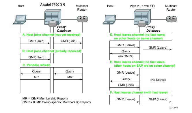
Figure 41 illustrates the basic IGMP message processing by the 7750 SR in several situations.
Figure 41: IGMP Message Processing
Scenario A: A host joins a multicast group (TV channel) which is not yet being received by other hosts on the router, and thus is not yet present in the proxy database. The 7750 SR adds the group to the proxy database and sends a new IGMP Join group-specific membership report upstream to the multicast router.
Scenario B: A host joins a channel which is already being received by one or more hosts on the 7750 SR, and thus is already present in the proxy database. No upstream IGMP report is generated by the router.
Scenario C: The multicast router will periodically send IGMP queries to the router, requesting it to respond with generic membership reports. Upon receiving such a query, the 7750 SR will compile a report from its proxy database and send it back to the multicast router.
In addition, the router will flood the received IGMP query to all hosts (on SAPs and spoke SDPs), and will update its proxy database based on the membership reports received back.
Scenario D: A host leaves a channel by sending an IGMP leave message. If fast-leave is not enabled, the router will first check whether there are other hosts on the same SAP or spoke SDP by sending a query. If no other host responds, the 7750 SR removes the channel from the SAP. In addition, if there are no other SAPs or spoke SDPs with hosts subscribing to the same channel, the channel is removed from the proxy database and an IGMP leave report is sent to the upstream Multicast Router.
Scenario E: A host leaves a channel by sending an IGMP leave message. If fast-leave is not enabled, the router will check whether there are other hosts on the same SAP or spoke SDP by sending a query. Another device on the same SAP or spoke SDP still wishes to receive the channel and responds with a membership report. Thus the 7750 SR does not remove the channel from the SAP.
Scenario F: A host leaves a channel by sending an IGMP leave report. Fast-leave is enabled, so the 7750 SR will not check whether there are other hosts on the same SAP or spoke SDP but immediately removes the group from the SAP. In addition, if there are no other SAPs or spoke SDPs with hosts subscribing to the same group, the group is removed from the proxy database and an IGMP leave report is sent to the upstream multicast router.
 
IGMP Filtering
A provider may want to block receive or transmit permission to individual hosts or a range of hosts. To this end, the Alcatel-Lucent 7750 SR supports IGMP filtering. Two types of filter can be defined:
 
Multicast VPLS Registration (MVR)
Multicast VPLS Registration (MVR) is a bandwidth optimization method for multicast in a broadband services network. MVR allows a subscriber on a port to subscribe and unsubscribe to a multicast stream on one or more network-wide multicast VPLS instances.
MVR assumes that subscribers join and leave multicast streams by sending IGMP join and leave messages. The IGMP leave and join message are sent inside the VPLS to which the subscriber port is assigned. The multicast VPLS is shared in the network while the subscribers remain in separate VPLS services. Using MVR, users on different VPLS cannot exchange any information between them, but still multicast services are provided.
On the MVR VPLS, IGMP snooping must be enabled. On the user VPLS, IGMP snooping and MVR work independently. If IGMP snooping and MVR are both enabled, MVR reacts only to join and leave messages from multicast groups configured under MVR. Join and leave messages from all other multicast groups are managed by IGMP snooping in the local VPLS. This way, potentially several MVR VPLS instances could be configured, each with its own set of multicast channels.
MVR by proxy — In some situations, the multicast traffic should not be copied from the MVR VPLS to the SAP on which the IGMP message was received (standard MVR behavior) but to another SAP. This is called MVR by proxy.
Figure 42: MVR and MVR by Proxy
Layer 3 Multicast Load Balancing
Layer 3 multicast load balancing establishes a more efficient distribution of Layer 3 multicast data over ECMP and LAG links. Operators have the option to redistribute multicast groups over ECMP and/or LAG links if the number of links changes either up or down.
When implementing this feature, there are several considerations. When multicast load balancing is not configured, the distribution remains as is. Multicast load balancing is based on the number of “s,g” groups. This means that bandwidth considerations are not taken into account. The multicast groups are distributed over the available links as joins are processed. When link failure occurs, the load is distributed on the failed channel to the remaining channels so multicast groups are evenly distributed over the remaining links. When a link is added (or failed link returned) all multicast joins on the added link(s) are allocated until a balance is achieved.
When multicast load balancing is configured, but the channels are not found in the multicast-info-policy, then multicast load balancing is based on the number of “s,g” groups. This means that bandwidth considerations are not taken into account. The multicast groups are distributed over the available links as joins are processed. The multicast groups are evenly distributed over the remaining links. When link failure occurs, the load is distributed on the failed channel to the remaining channels. When a link is added (or failed link returned) all multicast joins on the added link(s) are allocated until a balance is achieved.A manual redistribute command enables the operator to re-evaluate the current balance and, if required, move channels to different links to achieve a balance.A timed redistribute parameter allows the system to automatically, at regular intervals, redistribute multicast groups over available links. If no links have been added or removed from the ECMP/LAG interface, then no redistribution is attempted.
When multicast load balancing is configured, multicast groups are distributed over the available links as joins are processed based on bandwidth configured for the specified group address. If the bandwidth is not configured for the multicast stream then the configured default value is used.
If link failure occurs, the load is distributed on the failed channel to the remaining channels. The bandwidth required over each individual link is evenly distributed over the remaining links.
When an additional link is available for a given multicast stream, then it is considered in all multicast stream additions applied to the interface. This multicast stream is included in the next scheduled automatic rebalance run. A rebalance run re-evaluates the current balance with regard to the bandwidth utilization and if required, move multicast streams to different links to achieve a balance.
A rebalance, either timed or executing the mc-ecmp-rebalance command, should be administered gradually in order to minimize the effect of the rebalancing process on the different multicast streams. If multicast re-balancing is disabled and subsequently (re)enabled, keeping with the rebalance process, the gradual and least invasive method is used to minimize the effect of the changes to the customer.
By default multicast load balancing over ECMP links is enabled and set at 30 minutes.
The rebalance process can be executed as a low priority background task while control of the console is returned to the operator. When multicast load rebalancing is not enabled, then ECMP changes will not be optimized, however, when a link is added occurs an attempt is made to balance the number of multicast streams on the available ECMP links. This however may not result in balanced utilization of ECMP links.
Only a single mc-ecmp-rebalance command can be executed at any given time, if a rebalance is in progress and the command is entered, it is rejected with the message saying that a rebalance is already in progress. A low priority event is generated when an actual change for a given multicast stream occurs as a result of the rebalance process.
 
IGMP State Reporter
The target application for this feature is linear TV delivery. In some countries, wholesale Service Providers are obligated by the government regulation to provide information about channel viewership per subscriber to retailers.
A service provider (wholesaler or retailer) my use this information for:
The information about channel viewership is based on IGMP states maintained per each subscriber host. Each event related to the IGMP state creation is recorded and formatted by the IGMP process. The formatted event is then sent to another task in the system (Exporter), which allocates a TX buffer and start a timer.
The event is then be written by the Exporter into the buffer. The buffer in essence corresponds to the packet that will contain a single event or a set of events. Those events are transported as data records over UDP transport to an external collector node. The packet itself has a header followed by a set of TLV type data structures, each describing a unique filed within the IGMP event.
The packet is transmitted when it reaches a preconfigured size (1400bytes), or when the timer expires, whichever comes first. Note that the timer started when the buffer was initially created.
The receiving end (collector node) accepts the data on the destination UDP port. It must be aware of the data format so that it can interpret incoming data accordingly. The implementation details of the receiving node are outside of the scope of this description and are left to the network operator.
The IGMP state recording per subscriber host must be supported for hosts which are replicating multicast traffic directly as well as for those host that are only keeping track of IGMP states for the HQoS Adjustment purpose. The latter will be implemented via redirection and not the Host Tracking (HT) feature as originally proposed. The IGMP reporting must differentiate events between direct replication and redirection.
It further distinguish events that are related to denial of IGMP state creation (due to filters, MCAC failure, etc.) and the ones that are related to removal of an already existing IGMP state in the system.
 
 
IGMP Data Records
Each IGMP state change generates a data record that is formatted by the IGMP task and written into the buffer. IGMP state transitions configured statically through CLI are not reported.
In order to minimize the size of the records when transported over the network, most fields in the data record are HEX coded (as opposed to ASCII descriptive strings).
Each data record has a common header as shown in Figure 43:
Figure 43: Common IGMP Data Record Header
Application:
Event:
Length:
16 bit Sequence Number
Timestamp:
TLVs describing the IGMP state record will have the following structure:
Figure 44: Data Record Field TLV Structure
 
The redirection destination TLV is a mandatory TLV that is sent only in cases where redirection is enabled. It contains two 32 bit integer numbers. The first number identifies the VRF where IGMPs are redirected; the second number identifies the interface index.
Optional fields can be included in the data records according to the configuration.
In IGMPv3, if an IGMP message (Join or Leave) contains multiple multicast groups or a multicast group contains multiple IP sources, only a single event is generated per group-source combination. In other words, data records are transmitted with a single source IP address and multiple mcast group addresses or a single multicast group address with multiple source IP addresses, depending on the content of the IGMP message. (*,G)
 
Transport Mechanism
Data is transported via UDP socket. Destination IP address, the destination port and the source IP address are configurable. The default UDP source and destination port number is 1037.
Upon the arrival of an IGMP event, the Exporter allocates a buffer for the packet (if not already allocated) and starts writing the events into the buffer (packet). Along with the initial buffer creation, a timer is started. The trigger for the transmission of the packet is either the TX buffer being filled up to 1400B (hard coded value), or the timer expiry, whichever comes first.
The source IP address is configurable within GRT (by default system IP), and the destination IP address can be reachable only via GRT. The source IP address is modified via system>security>source-address>application CLI hierarchy.
The receiving end (the collector node) collects the data and process them according to the formatting rules defined in this document. The capturing and processing of the data on the collector node is outside of the context of this description.
It should be noted that the processing node will need to have sufficient resources to accept and process packets that contain information about every IGMP state change for every host from a set of network BRASes that are transporting data to this particular collector node.
Multicast Reporter traffic will be marked as BE (all 6 DSCP bits are set to 0) exiting our system.
 
HA Compliance
IGMP Events are synchronized between two CPMs before they are transported out of the system.
 
QoS Awareness
IGMP Reporter is a client of sgt-qos so that DSCP/dot1p bits can be appropriately be marked when egressing the system.
 
Hardware Support
The following hardware is supported on the 7750 platform.
IOM support: IOM3, HSMDAv2, Ethernet based non HS-MDAs
Chassis mode: B, C, and D.
 
IGMP Reporting Caveats
The following are not supported:
Multicast Support over Subscriber Interfaces in Routed CO Model
Applications for multicast over Subscriber Interfaces in Routed CO ESM model can be divided in two main categories:
Residential customers where the driver applications are:
For the business customers, the main drivers are enterprise multicast and Internet multicast applications.
On multicast-capable ANs, a single copy of each multicast stream is delivered over a separate regular IP interface. AN would then perform the replication. This is how multicast would be deployed in a Routed CO environment with 7x50s.
On legacy, non-multicast ANs , or in environments with low volume multicast traffic where it is not worth setting up a separate multicast topology (from BNG to AN), multicast replication is performed via subscriber-interfaces in 7x50. There are differences in replicating multicast traffic on IPoE vs PPPoX which will be described in subsequent sessions.
An example of a business connectivity model is shown in Figure 45.
Figure 45: A Typical Business Connectivity Model
In this example, HSI is terminated in a Global Routing Table (GRT) whereas VPRN services are terminated in Wholesale/Retail VPRN fashion, with each customer using a separate VPRN.
The actual connectivity model that will be deployed depends on many operational aspects that are present in the customer environment.
Multicast over subscriber-interfaces in a Routed CO model is supported for both types of hosts, IPoE and PPPoE which can be simultaneously enabled on a shared SAP.
There are some fundamental differences in multicast behavior between two host types (IPoE and PPPoX). The differences will be discussed further in the next sections.
 
Hardware Support
Multicast over subscriber interfaces is supported on all FP2 based hardware that supports Routed CO model. This includes:
Chassis modes B, C and D are supported.
 
Multicast Over IPoE
There are several deployment scenarios for delivering multicast directly over subscriber hosts:
There are two modes of operation for subscriber multicast that can be chosen to address the above mentioned deployment scenarios:
1.
2.
In all deployment scenarios and modes of operation the IGMP states per source IP address of the incoming IGMP message is maintained. This source IP address might represent a subscriber hosts or the AN (Proxy mode).
 
Per SAP Replication Mode
In the per SAP replication mode a single copy of the multicast channel is forwarded per SAP. In other words, if a subscriber (in 1:1 mode) or a group of subscribers (in N:1 mode) have multiple hosts and all of them are subscribed to the same multicast group (watching the same channel), then only a single copy of the multicast stream for that group will be sent. The destination MAC address will always be a multicast MAC (there will be no conversion to unicast mac address).
IGMP states are maintained per subscriber host and per SAP.
 
Per SAP Queue
Multicast traffic over subscribers in a per SAP replication mode is flowing via a SAP queue which is outside of the subscriber queues context. Sending the multicast traffic over the default SAP queue is characterized by:
Redirection of multicast traffic via internal queues in case that the SAP queue in subscriber environment is disabled (sub-sla-mgmt>single-sub-parameters>profiled-traffic-only). This is applicable only to 1:1 subscriber model.
 
IPoE 1:1 Model (Subscriber per VLAN/SAP) — No IGMP in AN
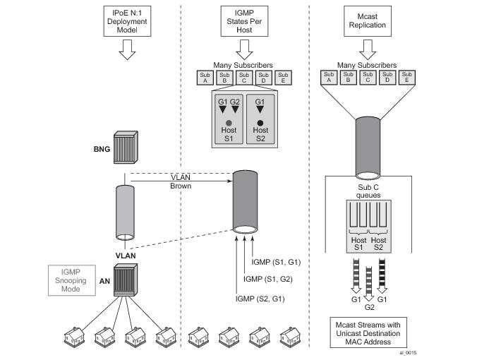
This model is shown in Figure 46. The AN is not IGMP aware, all replications are performed in the BNG. From the BNG perspective this deployment model has the following characteristics:
Figure 46: 1:1 Model
IPoE N:1 Model (Service per VLAN/SAP) — IGMP Snooping in the AN
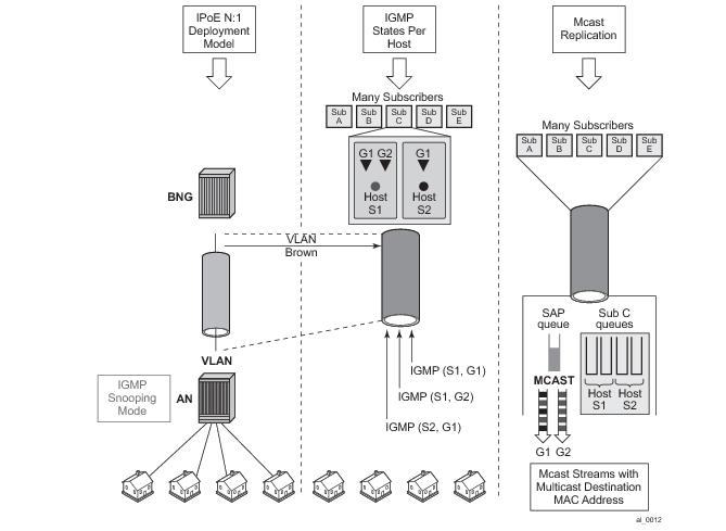
This model is shown in Figure 47. The AN is IGMP aware and is participating in multicast replication. From the BNG perspective this deployment model has the following characteristics:
Figure 47: - N:1 Model - AN in IGMP Snooping Mode
 
IPoE N:1 Model (Service per VLAN/SAP) — IGMP Proxy in the AN
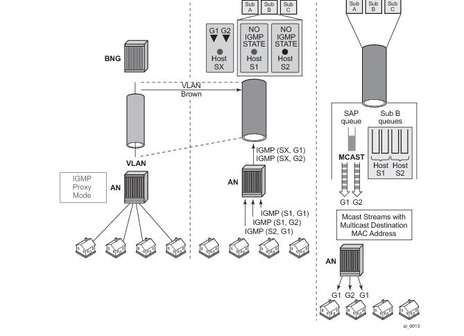
This model is shown in Figure 48. The AN is configured as IGMP Proxy node and is participating in downstream multicast replication. IGMP messages from multiple sources (subscribers hosts) for the same multicast group are consolidated in the AN into a single IGMP messages. This single IGMP message has the source IP address of the AN.
From the BNG perspective this deployment model has the following characteristics:
IGMP Joins are accepted from the source IP address that is different from any of the subscriber’ IP addresses already existing in the BNG. This will be controlled via an IGMP filter on a per group-interface level assuming that the IGMP processing for subscriber hosts is disabled with the no sub-hosts-only command under the router/service vprn>igmp>group-interface CLI hierarchy. In this case all IGMP messages that cannot be related to existing hosts will be treated in the context of the sap while IGMP messages from the existing hosts will be treated in the context of the subscriber hosts.
In the following example, IGMPs from the source IP address <ip> is accepted even though there is no subscriber-host with that IP addresses present in the system. An IGMP state will be created under the sap context (service per vlan, or N:1 model) for the group <pref-definition>. All other IGMP messages originated from non-subscriber hosts will be rejected. IGMP messages for subscriber hosts will be processed according to the igmp-policy applied to each subscriber host.
configure 
     service vprn <id>
          igmp
               group-interface <name>  			
                    import <policy-name>
         
configure
     router
          policy-options
               begin
                    prefix-list <pref-name>
                         prefix <pref-definition> 
               
                    policy-statement proxy-policy
                	entry 1
                  	  from 
                      	    group-address <pref-name>
                            source-address <ip>
                            protocol igmp
                        exit
                   	action accept
                   	exit
                      exit
                      default-action reject 
 
This functionality (accepting IGMP from non-subscriber hosts) can be disabled with the following flag.
 
configure 
	service vprn <id>
		igmp
			group-interface <name> 			
    sub-host-only
 
In this case only per host IGMP processing will be allowed.
Figure 48: N:1 Model - AN in Proxy mode
 
Per Subscriber Host Replication Mode
In this mode a multicast stream is transmitted per subscriber hosts for each registered multicast group (channel). As a result, multiple copies of the same multicast stream destined to different destinations can be transmitted over the same SAP. In this case traffic flows within the subscriber queues and consequently it is accounted in HQoS. As a result, HQoS Adjustment is not needed. Each copy of the same multicast stream have a unique unicast destination MAC addresses. The per host unicast MAC destination addresses are necessary to differentiate multiple copies between different receivers on the same SAP.
Per host replication mode can be enabled on a subscriber basis with the per-host-replication command in the subscriber-management>igmp-policy hierarchy.
 
IPoE 1:1 Model (Subscriber per VLAN/SAP) — No IGMP in AN
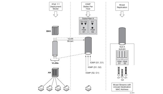
This model is shown in Figure 49. The AN is NOT IGMP aware and multicast replication is performed in the BNG. Multicast streams are sent directly to the hosts using their unicast MAC addresses. HQoS Adjustment is NOT needed as multicast traffic is flowing through subscriber queues. From the BNG perspective this deployment model has the following characteristics:
 
Figure 49: 1:1 Model
 
IPoE N:1 Model (Service per VLAN/SAP) — No IGMP in the AN
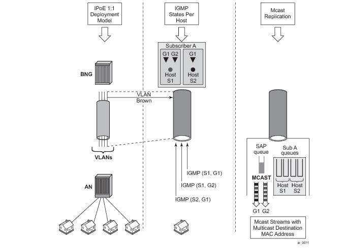
This model is shown in Figure 50. The AN is not IGMP aware and is not participating in multicast replication. From the BNG perspective this deployment model has the following characteristics:
 
Figure 50: N:1 Model — No IGMP in the AN
Multicast Over PPPoE
In a PPPoE environment, multicast replication is performed per session (host) regardless of whether those sessions are shared per SAP or they reside on individual SAPs. This is due to the point-to-point nature of PPPoE sessions. There will be no need for HQoS Adjustment as multicast is part of the PPPoE session traffic that is flowing via subscriber queues. Multicast packets are sent with unicast MAC address to each CPE. PPP protocol field is set to IP and the destination IP address is the multicast group address for each unique session ID (Figure 51).
Figure 51: Multicast IPv4 Address and Unicast MAC Address in PPPoE Subscriber Multicast
 
IGMP Flooding Containment
The query function in IGMP can cause some unintended flooding in N:1 IPoE deployment model with AN in the IGMP snooping mode. By maintaining IGMP session states per host, it is assumed that the IGMP interaction between multicast receivers and the BNG will be on a one-to-one basis. Upon arrival of an IGMP leave from a host for a specific multicast group, the IGMP querier would normally multicast a group-specific query (fast-leave). In N:1 model with sap-replication mode enabled, 7x50 will send a group-specific query (fast-leave) only when it receives the IGMP leave message for the last group shared amongst all subscribers on this SAP.
 
IGMP Timers
IGMP timers are maintained under the following hierarchy:
configure>router>igmp
configure>service vprn>igmp
As it can be seen, the igmp timers are controlled on a per routing instance (VRF or GRT) level.
The timer values are used to:
However, the timers can be different for hosts and redirected interface in case that redirection between VRFs is enabled.
 
IGMP Query Intervals
IGMP query related intervals (query-interval, query-last-member-interval, query-response-interval, robust-count) are configured on a global router/vprn IGMP level. They are used to determine the IGMP timeout states and the rates at which queries are transmitted.
In case of redirection, the subscriber-host IGMP state will determine the IGMP state on the redirected interface, assuming that IGMP messages are not directly received on the redirected interface (for example from the AN performing IGMP forking). For example if the redirected interface is not receiving IGMP messages from the downstream node, then the IGMP state under redirected interface will be removed simultaneously with the removal of the IGMP state for the subscriber host (due to leave or a timeout).
In case that the redirected interface is receiving IGMP message directly from the downstream node, the IGMP states on that redirected interface will be driven by those direct IGMP messages.
For example, an IGMP host in VRF1 has an expiry time of 60 seconds and the expiry time defined under the VRF2 where multicast traffic is redirected is set to 90 seconds. The IGMP state will time out for the host in VRF1 after 60s, and if no host has joined the same multicast group in VRF2 (where redirected interface resides), the IGMP state will be removed there too.
If a join was received directly on the redirection interface in VRF2, the IGMP state for that group will be maintained for 90s, regardless of the IGMP state for the same group in VRF1.
 
HQoS Adjustment
HQoS Adjustment is required in the scenarios where subscriber multicast traffic flow is disassociated from subscriber queues. In other words, the unicast traffic for the subscriber is flowing through the subscriber queues while at the same time multicast traffic for the same subscriber is explicitly (through redirection) or implicitly (per-sap replication mode) redirected through a separate non-subscriber queue. In this case HQoS Adjustment can be deployed where preconfigured multicast bandwidth per channel is artificially included in HQoS. For example, bandwidth consumption per multicast group must be known in advance and configured within the 7x50. By keeping the IGMP state per host, the bandwidth for the multicast group (channel) to which the host is registered is known and is deducted as consumed from the aggregate subscriber bandwidth.
The multicast bandwidth per channel must be known (this is always an approximation) and provisioned in the BNG node in advance.
In PPPoE and in IPoE per host replication environment, HQoS Adjustment is not needed as multicast traffic is unicasted to each subscriber and therefore is flowing through subscriber queues.
For HQoS Adjustment, the channel bandwidth definition and association with an interface is the same as in the MCAC case. This is a departure from the legacy HT channel bandwidth definition which is done via multicast-info-policy.
Example of HQoS adjustment:
Channel definition:
configure
	router 
		mcac	
			policy <name>
				<channel definition>


Channel bandwidth definition policy can be applied under:
configure
	service vprn <id>
		igmp
			group-interface <grp-if-name>
				mcac
					policy <mcac-policy-name>  
 
configure
	router/service vprn
		igmp
			interface <name>
				mcac
					policy <mcac-policy-name>
 
configure 
	service vprn <id>
		igmp								
			group-interface fwd-service <svc-id> <grp-if-name>  
				mcac
  policy <mcac-policy-name>
 
Enabling HQoS adjustment:
configure
    subscriber-management
    	igmp-policy <name>
    		egress-rate-modify [egress-aggregate-rate-limit | scheduler <name>]
 
Applying HQoS adjustment to the subscriber:
configure
    subscriber-management
    	sub-profile <name>
    		igmp-policy <name>
 
In order to activate HQoS adjustment on the subscriber level, the sub-mcac-policy must be enabled under the subscriber via the following CLI:
configure
	subscriber-management
		sub-mcac-policy <pol-name>			
			no shutdown
 
configure
	subscriber-management
		sub-profile <name>
			sub-mcac-policy <pol-name> 	
 
The adjusted bandwidth during operation can be verified with the following commands (depending whether agg-rate-limit or scheduler-policy is used):
*B:BNG-1# show service active-subscribers subscriber "sub-1" detail  
===============================================================================
Active Subscribers
===============================================================================
-------------------------------------------------------------------------------
Subscriber sub-1 
-------------------------------------------------------------------------------
I. Sched. Policy : up-silver             
E. Sched. Policy : N/A                              E. Agg Rate Limit: 4000
I. Policer Ctrl. : N/A                              
E. Policer Ctrl. : N/A                              
Q Frame-Based Ac*: Disabled                         
Acct. Policy     : N/A                              Collect Stats    : Enabled
Rad. Acct. Pol.  : sub-1-acct                         
Dupl. Acct. Pol. : N/A                              
ANCP Pol.        : N/A                              
HostTrk Pol.     : N/A                              
IGMP Policy      : sub-1-IGMP-Pol                     
Sub. MCAC Policy : sub-1-MCAC                          
NAT Policy       : N/A                              
Def. Encap Offset: none                             Encap Offset Mode: none
Avg Frame Size   : N/A                              
Preference       : 5                                
Sub. ANCP-String : "sub-1"
Sub. Int Dest Id : ""
Igmp Rate Adj    : -2000                            
RADIUS Rate-Limit: N/A                              
Oper-Rate-Limit  : 2000
...
-------------------------------------------------------------------------------
*B:BNG-1#
Consider a different example with a scheduler instead of agg-rate-limit:
*A:Dut-C>config>subscr-mgmt>sub-prof# info 
----------------------------------------------
            igmp-policy "pol1"
            sub-mcac-policy "smp"
            egress
                scheduler-policy "h1"
                    scheduler "t2" rate 30000  
                exit
            exit
----------------------------------------------
 
*A:Dut-C>config>subscr-mgmt>igmp-policy# info 
----------------------------------------------
            egress-rate-modify scheduler "t2"
            redirection-policy "mc_redir1"
----------------------------------------------
Now, assume that the subscriber joins now a new channel with bandwidth of 1mbps (1000 kbps).
A:Dut-C>config>subscr-mgmt>sub-prof>egr>sched># show qos scheduler-hierarchy subscriber "sub_1" detail 
===============================================================================
Scheduler Hierarchy - Subscriber sub_1
===============================================================================
Ingress Scheduler Policy: 
Egress Scheduler Policy : h1
-------------------------------------------------------------------------------
Legend :
(*) real-time dynamic value
(w) Wire rates
B   Bytes
-------------------------------------------------------------------------------
Root (Ing)
|
No Active Members Found on slot 1
 
Root (Egr)
| slot(1)
|--(S) : t1  
|   |    AdminPIR:90000      AdminCIR:10000     
|   |
|   |
|   |    [Within CIR Level 0 Weight 0]
|   |    Assigned:0          Offered:0         
|   |    Consumed:0         
|   |
|   |    [Above CIR Level 0 Weight 0]
|   |    Assigned:0          Offered:0         
|   |    Consumed:0         
|   |    TotalConsumed:0         
|   |    OperPIR:90000     
|   |
|   |    [As Parent]
|   |    Rate:90000     
|   |    ConsumedByChildren:0         
|   |                                 
|   |
|   |--(S) : t2  
|   |   |    AdminPIR:29000      AdminCIR:10000(sum)       <==== bw 1000 from igmp substracted
|   |   |
|   |   |
|   |   |    [Within CIR Level 0 Weight 1]
|   |   |    Assigned:10000      Offered:0         
|   |   |    Consumed:0         
|   |   |
|   |   |    [Above CIR Level 1 Weight 1]
|   |   |    Assigned:29000      Offered:0                 <==== bw 1000 from igmp substracted    
|   |   |    Consumed:0         
|   |   |
|   |   |
|   |   |    TotalConsumed:0         
|   |   |    OperPIR:29000                                 <==== bw 1000 from igmp substracted
|   |   |
|   |   |    [As Parent]
|   |   |    Rate:29000                                     <==== bw 1000 from igmp substracted
|   |   |    ConsumedByChildren:0         
|   |   |
|   |   |
|   |   |--(S) : t3  
|   |   |   |    AdminPIR:70000      AdminCIR:10000     
|   |   |   |
|   |   |   |
|   |   |   |    [Within CIR Level 0 Weight 1]
|   |   |   |    Assigned:10000      Offered:0         
|   |   |   |    Consumed:0         
|   |   |   |
|   |   |   |    [Above CIR Level 1 Weight 1]
|   |   |   |    Assigned:29000      Offered:0         
|   |   |   |    Consumed:0         
|   |   |   |
|   |   |   |
|   |   |   |    TotalConsumed:0         
|   |   |   |    OperPIR:29000     
|   |   |   |
|   |   |   |    [As Parent]
|   |   |   |    Rate:29000           
|   |   |   |    ConsumedByChildren:0         
|   |   |   |
 
*A:Dut-C>config>subscr-mgmt>igmp-policy# show service active-subscribers sub-mcac 
===============================================================================
Active Subscribers Sub-MCAC
===============================================================================
Subscriber                             : sub_1
MCAC-policy                            : smp (inService)
In use mandatory bandwidth             : 1000
In use optional bandwidth              : 0
Available mandatory bandwidth          : 1147482647
Available optional bandwidth           : 1000000000
-------------------------------------------------------------------------------
Subscriber                             : sub_2
MCAC-policy                            : smp (inService)
In use mandatory bandwidth             : 0
In use optional bandwidth              : 0
Available mandatory bandwidth          : 1147483647
Available optional bandwidth           : 1000000000
-------------------------------------------------------------------------------
-------------------------------------------------------------------------------
Number of Subscribers : 2
===============================================================================
*A:Dut-C# 
 
 
*A:Dut-C# show service active-subscribers subscriber "sub_1" detail 
===============================================================================
Active Subscribers
===============================================================================
-------------------------------------------------------------------------------
Subscriber sub_1 (1)
-------------------------------------------------------------------------------
I. Sched. Policy : N/A                              
E. Sched. Policy : h1                               E. Agg Rate Limit: Max
I. Policer Ctrl. : N/A                              
E. Policer Ctrl. : N/A                              
Q Frame-Based Ac*: Disabled                         
Acct. Policy     : N/A                              Collect Stats    : Disabled
Rad. Acct. Pol.  : N/A                              
Dupl. Acct. Pol. : N/A                              
ANCP Pol.        : N/A                              
HostTrk Pol.     : N/A                              
IGMP Policy      : pol1                             
Sub. MCAC Policy : smp                              
NAT Policy       : N/A                              
Def. Encap Offset: none                             Encap Offset Mode: none
Avg Frame Size   : N/A                              
Preference       : 5                                
Sub. ANCP-String : "sub_1"
Sub. Int Dest Id : ""
Igmp Rate Adj    : N/A                              
RADIUS Rate-Limit: N/A                              
Oper-Rate-Limit  : Maximum                          
...
===============================================================================
*A:Dut-C# 
 
 
*A:Dut-C# show subscriber-mgmt igmp-policy "pol1"                   
===============================================================================
IGMP Policy pol1
===============================================================================
Import Policy                         : 
Admin Version                         : 3
Num Subscribers                       : 2
Host Max Group                        : No Limit
Host Max Sources                      : No Limit
Fast Leave                            : yes
Redirection Policy                    : mc_redir1
Per Host Replication                  : no
Egress Rate Modify                    : "t2"
Mcast Reporting Destination Name      : 
Mcast Reporting Admin State           : Disabled
===============================================================================
*A:Dut-C# 


Host Tracking (HT) Considerations
HT is a light version of HQoS Adjustment feature. The use of HQoS Adjustment functionality in place of HT is strongly encouraged.
When HT is enabled, the AN will fork off (duplicate) the IGMP messages on the common mcast SAP to the subscriber SAP. IGMP states will not be fully maintained per sub-host in the BNG, instead they will be only tracked (less overhead) for bandwidth adjustment purposes.
Example of HT
Channel Definition:
configure
    mcast-management 
		multicast-info-policy <name>
			<channel to b/w mapping definition>
Applying channel definition policy on a router/VPRN global level:
configure>router>multicast-info-policy <name>
configure>service>vrpn>multicast-info-policy <name>
Defining the rate object on which HT will be applied:
configure
    subscriber-management
    	host-tracking-policy <name>
    		egress-rate-modify [agg-rate-limit | scheduler <sch-name>]
 
Applying the HT to the subscriber:
configure
    subscriber-management
    	sub-profile <name>
    		host-tracking-policy <name>  => mutually exclusive with igmp-policy
HQoS Adjust Per Vport
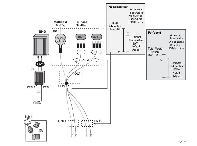
HQoS Adjust per Vport can be used in environments where vport represents a physical medium over which traffic for multiple subscribers is shared. Typical example of this scenario is shown in Figure 52. Multicast traffic within 7x50 is taking a separate path from unicast traffic, only for the two traffic flows to merge later in the PON (represented by vport in 7x50) and ONT (represented by subscriber in 7x50).
Figure 52: HQoS Adjustment per Subscriber and Vport
A single copy of each channel is replicated on the PON as long as there is at least one subscriber on that PON interested in this channel (has joined the IGMP group).
7x50 monitors IGMP Joins at the subscriber level and consequently the channel bandwidth is subtracted from the current Vport rate limit only in the case that this is the first channel flowing through the corresponding PON. Otherwise, the Vport bandwidth is not modified. Similarly, when the channel is removed from the last subscriber on the PON, the channel bandwidth is returned to the VPort.
Association between the Vport and the subscriber is performed via inter-destination-string or svlan during the subscriber setup phase. Inter-destination-string can be obtained either via Radius or LUDB. In case that the association between the Vport and the subscriber is performed based on the svlan (as specified in sub-sla-mgmt under the sap/msap), then the destination string under the Vport must be a number matching the svlan.
The mcac-policy (channel definition bandwidth) can be applied on the group interface under which the subscribers are instantiated or in case of redirection under the redirected-interface.
In a LAG environment, the Vport instance is instantiated per member lag link on the IOM. For accurate bandwidth control, it is prerequisite for this feature that subscriber traffic hashing is performed per Vport.
The CLI structure is as follows.
configure
	port <port-id>
		ethernet
			access
				egress
					vport <name>
						egress-rate-modify						
agg-rate-limit <rate>
						host-match <destination-string>
						port-scheduler-policy <port-scheduler-policy-name>
						scheduler-policy <scheduler-policy-name>
 
configure
	port <port-id>
		sonnet-sdh
			path [<sonnet-sdh-index>]
				access				
egress
						vport <name>
							egress-rate-modify						
agg-rate-limit <rate>
							host-match <destination-string>
							port-scheduler-policy <port-scheduler-policy-name>
							scheduler-policy <scheduler-policy-name>
 
The Vport rate that will be affected by this functionality depends on the configuration:
The Vport rates can be displayed with the following two commands:
show port 1/1/5 vport name
qos scheduler-hierarchy port port-id vport vport-name
As an example:
*A:system-1# show port 1/1/7 vport 
========================================================================
Port 1/1/7 Access Egress vport
========================================================================
VPort Name    : isam1                             
Description   : (Not Specified)
Sched Policy  : 1                                 
Rate Limit    : Max                               
Rate Modify   : enabled                           
Modify delta  : -14000     
 
In this case, the configured Vport aggregate-rate-limit max value has been reduced by 14Mbps.
Similarly, if the Vport had a port-scheduling-policy applied, the max-rate value configured in the port-scheduling-policy would have been modified by the amount shown in the Modify delta output in the above command.
 
Multi-Chassis Redundancy
Modified Vport rate synchronization in multi-chassis environment relies on the synchronization of the subscriber IGMP states between the redundant nodes. Upon the switchover, the Vport rate on the newly active node is adjusted according to the current IGMP state of the subscribers associated with the Vport.
 
Scalability Considerations
It is assumed that the rate of the IGMP state change on the Vport level is substantially lower than on the subscriber level.
The reason for this is that the IGMP Join/Leaves are shared amongst subscribers on the same Vport (PON for example) and thus the IGMP state on the VPort level is changed only for the first IGMP Join per channel and the last IGMP leave per channel.


Redirection
Two levels of mcac can be enabled simultaneously and in such case this is referred as Hierarchical MCAC (H-MCAC). In case that redirection is enabled, H-MCAC per subscriber and the redirected interface is supported. However, mcac per group-interface in this case is not supported. Channel definition policy for the subscriber and the redirected interface is in this case referenced under the igmp->interface (redirected interface) CLI.
In case that redirection is disabled, H-MCAC for both, the subscriber and the group-interface is supported. The channel definition policy is in this case configured under the igmp>group-interface context.
Example:
Defining redirection action:
configure 
	router
		policy-options
			begin 
			policy-statement <name>
				default-action accept 
                multicast-redirection [fwd-service <svc id>] <interface name>
				exit
			exit
		exit
	exit
 
Applying redirection to the subscriber.
configure
	subscr-mgmt
		igmp-policy <name>
			import <policy-name>
         redirection-policy <name> 
 
Redirection that cross-connects GRT and VPRN is not supported. Redirection can be only performed between interfaces in the GRT, or between the interfaces in any of the VPRN (cross connecting VPRNs is allowed).
Redirection is also supported in a wholesaler/retailer VPRN model where redirected Layer 3 interface resides in the retailer VPRN.
 
Hierarchical Multicast CAC (H-MCAC)
MCAC is supported on three levels:
Two levels of MCAC can be enabled simultaneously and in such case this is referred as Hierarchical MCAC (H-MCAC). In case that redirection is enabled, H-MCAC per subscriber and the redirected interface is supported. However, MCAC per group-interface in this case is not supported. Channel definition policy for the subscriber and the redirected interface is in this case referenced under the igmp->interface (redirected interface) CLI hierarchy.
In case that redirection is disabled, H-MCAC for both, the subscriber and the group-interface is supported. The channel definition policy is in this case configured under the igmp>group-interface CLI hierarchy.
Examples
Note that the same channel definition and association with interfaces is used for MCAC/H-MCAC and HQoS Adjustment.
Channel definition:
configure
	router 
		mcac	
			policy <mcac-pol-name>
				bundle <bundle-name>
					bandwidth <kbps>
					channel <start-address> <end-address> bw <bw> [class {high|low}] [type {mandatory|optional}]
					:
					:
Channel bandwidth definition policy can be referenced under the:
configure
         		service vprn <id>
			igmp	
				 group-interface <grp-if-name>
					mcac
						policy <mcac-policy-name> 
 
configure
	router
		igmp
			interface <name>
				mcac
					policy <mcac-policy-name>
 
configure
	service vprn <id>
		igmp
			interface <if-name>
				mcac
					unconstrained-bw <bandwidth> mandatory-bw <mandatory-bw>
 
configure 
	service vprn <id>
		igmp								
			group-interface fwd-service <svc-id> <grp-if-name>  
				mcac
					policy <mcac-policy-name>
 
Enabling MCAC:
configure
	subscr-mgmt
		sub-mcac-policy <name>
			unconstrained-bw <bandwidth> mandatory-bw <mandatory-bw>
  
configure
	subscr-mgmt
		sub-profile <name>
			sub-mcac-policy <name>
    
configure
         		service vprn <id>
			igmp	
				group-interface <grp-if-name>
					mcac
						unconstrained-bw <bandwidth> mandatory-bw <mandatory-bw>	
 
configure
	router
		igmp
			interface <if-name>
				mcac
					unconstrained-bw <bandwidth> mandatory-bw <mandatory-bw>
 
configure
	service vprn <id>
		igmp
			interface <if-name>
				mcac
					unconstrained-bw <bandwidth> mandatory-bw <mandatory-bw>
 
 
MCAC Bundle Bandwidth Limit Considerations
In addition to multicast bandwidth limit that can be imposed on subscribers, group-interfaces or regular interfaces, there is another multicast bandwidth limit that can be imposed on a group of channels (channel bundle).
The MCAC policy, aside from the channel bandwidth definitions, could optionally contain this bandwidth cap for the group of channels:
config>router>mcac# info 
----------------------------------------------
        policy "test"
            bundle "test" create
                bandwidth 100000
                channel 225.0.0.10 225.0.0.10 bw 10000 type mandatory
                channel 225.0.0.11 225.0.0.15 bw 5000 type mandatory
                channel 225.0.0.20 225.0.0.30 bw 5000 type optional
            exit
        exit
 
This can be used to prevent a single set of channels from monopolizing MCAC bandwidth allocated to the entire interface. The bandwidth of each individual bundle will be capped to some value below the interface MCAC bandwidth limit, allowing each bundle to have its own share of the interface MCAC bandwidth.
In most cases, the bandwidth limit per bundle is not necessary to configure. The aggregate limit per all channels as defined under the subscriber/interface will cover majority of scenarios. In case that one wants to explore the bundle bandwidth limits and how they affect MCAC behavior, the following text will help understanding this topic.
To further understand how various MCAC bandwidth limits are applied, one need to understand the concept of the mandatory bandwidth that is pre-allocated in the following way:
1.
2.
config>router>igmp# info 
----------------------------------------------
            interface "ge-1/1/1"
                mcac
                    unconstrained-bw 10000 mandatory-bw 2000
                exit
            exit
          
The bundle bandwidth limit poses a problem when the MCAC policy is applied under the group-interface. The reason is that the group-interface represents the aggregation point for the subscribers and their bandwidth. As such it is natural that the any aggregated bandwidth limit under the group interface be larger than the bandwidth limit applied to any individual subscriber under it. Since the MCAC policy, along with the bundle bandwidth limit, is inherited by all subscribers under the group-interface, the exhaustion of the bundle bandwidth limit under the group interface will coincide with the exhaustion of the bundle bandwidth limit of any individual subscriber. This will result in a single subscriber starving out of multicast bandwidth the remaining subscribers under the same group-interface. While it is perfectly acceptable for the subscribers to inherit the multicast channel definition from the group-interface, for the above reasons it is not acceptable that the subscriber inherit the bandwidth cap from the group-interface.
To remedy this situation, the MCAC bandwidth limits are independently configured under the group-interface level (aggregated level) and the subscriber level via the command unconstrained-bw <kbps> mandatory-bw <kbps>. The undesired bundle bandwidth cap in the MCAC policy will be ignored under the group-interface AND under the subscriber. However, the bundle bandwidth cap will be applied automatically to each SAP under the group interface. A SAP is a natural place for a bundle bandwidth limit since each channel on a SAP can be replicated only once and therefore the amount of pre-allocated mandatory bandwidth can be pre-calculated. This is obviously not the case for the group interface where single channel can be replicated multiple times (one per each SAP under the grp-if). Similarly, the same channel can be replicated multiple times for the same subscriber in per-host replication mode. Only subscribers in per-sap replication mode will warrant a single replication per channel. Therefore, if bundle cap is configured, it will be applied to limit the bandwidth of the bundle that is applied to a subscriber in a per-sap replication mode.
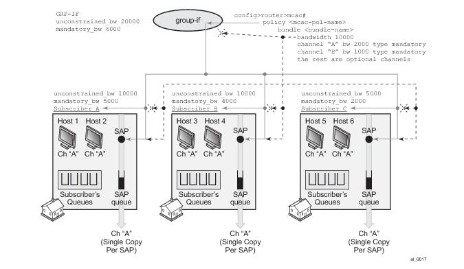
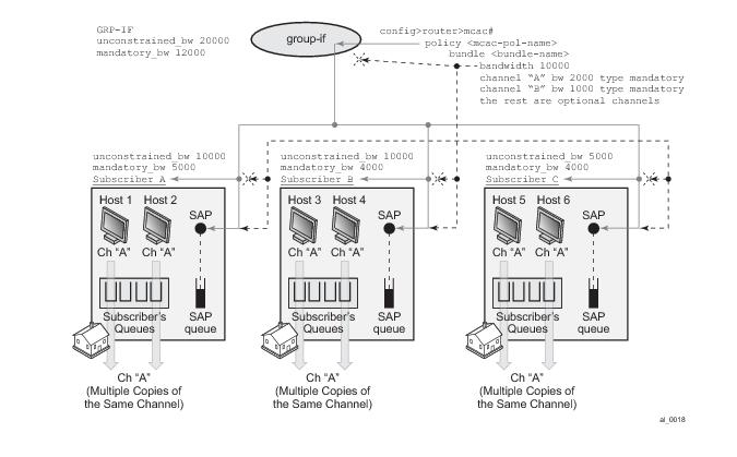
Figure 53 depicts MCAC related inheritances and MCAC bandwidth allocation model in per-sap replication mode.The MCAC policy is applied to the group interface and inherited by each subscriber as well as each SAP under the same group interface. However, the bundle bandwidth limit in the MCAC policy is ignored on the group-interface and under the subscriber (denoted by the red X in the figure). The bundle limit is applied only to each sap under the group-interface.
Overall (non-bundle) MCAC bandwidth limits are independently applied to the group-interface and the subscribers. According to our example, 20mbps of multicast bandwidth in total is allocated per group-interface. 6mbps of the 20mbps is allocated for mandatory channels. This leaves 14mbps of multicast bandwidth for the optional channels combined served on a first come first serve basis. Each physical replication (multiple replications of the same channel can occur, one per each SAP), counts towards the respective group-interface bandwidth limits.
Similar logic applies to the subscriber MCAC bandwidth limits which are applied per sub-profile.
Finally, each SAP can optionally contain the bundle bandwidth limit. Note that in a hierarchical MCAC fashion, if either of the bandwidth checks fails (SAP, sub or grp-if) the channel admission for the subscriber also fails.
In our example, 6 subscriber hosts watch the same channel but there are only 3 active replications (one per SAP). This would yield:
Figure 53: MCAC Policy Inheritance in Per-SAP Replication Mode
Figure 54 depicts behavior in per-host replication mode. MCAC policy inheritance flow is the same as in the previous example with the difference that the bundle limit has NO effect at all. Each host generates its own copy of the same multicast stream that is flowing via subscriber queues and not the SAP queue. Since each of the copies counts towards the subscriber or group-interface bandwidth limits, the multicast bandwidth consumption is higher in this example. This needs to be reflected in the configured multicast bandwidth limits. For example, the group-interface mandatory bandwidth limit is increased to 12mbps.
In our example, 6 subscriber hosts are still watching the same channel but now the number of replications is doubled from previous example. So the final tally for our MCAC bandwidth limit is as follows:
Figure 54: MCAC Policy Inheritance in Per-HOST Replication Mode
 
Determining MCAC Policy in Effect
Channel bandwidth definition (via MCAC policy) can be applied under the interface level (group-interface or regular interface):
configure>router/service>igmp>interface/grp-if
The following configuration options can lead to the confusion as to which MCAC policy is in effect:
The general, the rule is that the MCAC policy under the group-interface will always be in effect in cases where redirection is disabled. This is valid for subscriber or group-interface MCAC, hMCAC (subscriber and group-interface) and HQoS Adjust in per SAP replication mode.
If redirection is enabled, the MCAC policy under the group-interface will be ignored.
If redirection is enabled, but there is no MCAC policy applied under
the redirected interface1 (regardless of whether the MCAC policy under the group-interface is applied or not) then:
 
Multicast Filtering
Multicast filtering must be done per session (host) for IPoE and PPPoE. There are two types of filters that are supported:
1.
configure
	subscr-mgmt
		igmp-policy <name>
			import <policy-name>
         
An example of the filter definition is given below:
 
configure 
	router
		policy-options
			begin
			prefix-list <pref-name>
				prefix <pref-definition> 
			policy-statement <name>
				entry 1
					from 
						group-address <pref-name>
						source-address <ip>
						protocol igmp
					exit
					action accept
							exit
				exit
				default-action reject 
 
 
2.
 
Joining the Multicast Tree
The delivery of multicast to the subscribers-interface in a VPRN environment depends on the multicast deployment model (PIM, mBGP). In each model, a subscriber-interface is treated as a regular CE-PE interface that has registered v4 multicast listeners.
Wholesale/Retail Requirements
Multicast support on subscriber interfaces is supported in both wholesale/retail models:
Figure 55: Wholesale/Retail Multicast Support
The distinction between these two models is that in the case of LAC/LNS, the replication will be done further up in the network on an LNS node. This means that the traffic between LAC and LNS will be multiplied by the amount of replications.
 
QoS Considerations
In per-sap replication mode (which is applicable only to IPoE subscribers), multicast traffic is forwarded through the SAP queue which is outside of the subscribers queues and therefore not accounted in subscriber aggregate rate limit. HQoS Adjust is used to remedy this situation.
In case that the SAP queue is removed from the static SAP in IPoE 1:1 model (with profiled-only-traffic command), multicast traffic will flow via internal queues which cannot be tied into a port-scheduler as part of HQoS. Consequently, the port-scheduler max-rate as defined in the port-scheduler-policy will be used only to rate limit unicast traffic. In other words, the max-rate value in port-scheduler-policy must be lowered for the amount of anticipated multicast traffic that will flow via the port where port-scheduler-policy is applied.
A similar logic applies to per-sap replication mode on dynamic SAPs (MSAPs) even if the SAP queue is not removed. Although the multicast traffic is flowing via the SAP queue in this case, the SAP qos policy on MSAP cannot be changed from the default one. The default QoS policy on a SAP contains a single queue that is not parented by the port-scheduler.
Those restrictions do not apply to static SAPs where the SAP QoS policy can be customized and its queues consequently tied to the port-scheduler.
 
Redundancy Considerations
Subscriber IGMP states can be synchronized across multiple 7x50 nodes in order to ensure minimal interruption of (video delivery) service during network outages. The IGMP state of a subscriber-host in a 7x50 node is tied to the state of the underlying protection mechanism: MC-LAG and/or SRRP. For example, IGMP states will be activated only for subscribers that are anchored under the group-interfaces with master SRRP state or under the entire port under active MC-LAG.
In case of IGMP redirection, it must be ensured that the redirected interface (the interface to which multicast forwarding is redirected) is under the same MC-LAG as the subscriber. Otherwise, IGMP states on the redirected interface will be derived independently of the IGMP states for the subscriber from which IGMP messages are redirected.
In a nutshell the IGMP Synchronization process in conjunction with underlying access protection mechanisms will work as follows:
In all other cases, assuming that some protection mechanism in the access is present (SRRP or MC-LAG), the IGMP messages are discarded and consequently no IGMP state is updated. Similar logic applies to regular Layer 3 interfaces, where SRRP is replaced with VRRP.
Once the subscriber IGMP state is updated as a result of directly received IGMP message on an active2 subscriber (SRRP master of active MC-LAG), the sync IGMP message is sent to the standby subscriber over the Multi-Chassis Synchronization protocol. Synchronized IGMP states will be populated in Multi-chassis Synchronization (MCS) DB in all pairing 7x50 nodes.
The querier subscriber will not accept the IGMP update from the MCS database.
Note that in subscriber environment, SRRP should be always activated in dual-homing scenario, even if MC-LAG is deployed. SRRP in subscriber environment will ensure that downstream traffic is forwarded via the same node that is forwarding upstream traffic. In this fashion, accounting and QoS for the subscriber are consolidated within a single node.
To summarize, in multi-chassis environment with subscribers, IGMP synchronization enabled and an access layer protection mechanism in place (SRRP or MC-LAG), the behavior for is the following:
 
Redirection Considerations
For redirection and MCS to work simultaneously in predictable manner, the redirected interface and the corresponding subscribers have to be protected by the same MC-LAG. This binds the redirected interfaces and the subscriber-hosts to the same physical port(s).
The following describe some guidelines:
Briefly, IGMP states on Layer 3 interface are not VRRP aware. However, they are MC-LAG aware.
 

1
Redirected interface is the interface to which IGMP Joins are redirected from subscriber hosts.

2
Active and standby subscriber refers to the state of underlying protection mechanism (Master SRRP or active MC-LAG). Note that the subscribers themselves are always instantiated (or active) on both nodes. However, traffic forwarding over those subscribers will be driven by the state of the underlying protection mechanism (SRRP or MC-LAG). Hence the terms active and standby subscriber.