Flow-Information ::= < AVP Header: 1058 > 3GPP 29.212 §5.3.53
[ Flow-Description ] 3GPP 29.214 §5.3.8
[ ToS-Traffic-Class ] 3GPP 29.212 §5.3.15
[ Flow-Direction ] 3GPP 29.212 §5.3.65
*[ AVP ]
In the config>aaa CLI context, configure a diameter peer policy with one or multiple Diameter peers.
configure
aaa
diameter-peer-policy "diameter-peer-policy-1" create
description "Diameter peer policy"
applications gy
connection-timer 5
origin-host "bng.alcatel-lucent.com"
origin-realm "alcatel-lucent.com"
source-address 10.0.0.1
peer "peer-1" create
address 10.1.0.1
destination-host "server.alcatel-lucent.com"
destination-realm "alcatel-lucent.com"
no shutdown
exit
exit
exit
In the config>subscriber-mgmt CLI context, configure a diameter application policy:
– Specify the Diameter peer policy to use and optionally specific additional Gy application specific parameters (for example AVP format).
configure
subscriber-mgmt
diameter-application-policy "diameter-gy-policy-1" create
description "Diameter Gy policy"
application gy
diameter-peer-policy "diameter-peer-policy-1"
gy
avp-subscription-id subscriber-id type e164
include-avp
radius-user-name
exit
exit
exit
exit
configure
subscriber-mgmt
category-map "cat-map-1" create
description "Category Map"
credit-type time
category "cat-1" create
rating-group 1
queue 1 ingress-egress
exhausted-credit-service-level
pir 256
exit
exit
exit
exit
configure
subscriber-mgmt
credit-control-policy "cc-policy-1" create
description "Credit Control Policy"
credit-control-server diameter "diameter-gy-policy-1"
default-category-map "cat-map-1"
out-of-credit-action change-service-level
exit
exit
configure
subscriber-mgmt
sla-profile "sla-profile-3" create
description "SLA profile"
credit-control-policy "cc-policy-1"
exit
exit
|
•
|
subscription-id AVP (RFC 4006, §8,46) — This can be used to identify the subscribers on the PCRF. For the supported fields within the subscription-id AVP, refer to the 7750 SR OS Gx AVPs Reference Guide.
|
|
•
|
logical-access-id AVP (ETSI TS 283 034) — This will contain circuit-id from DHCPv4 Option (82,1) or interface-id from DHCPv6 option 18. The vendor-id will be set to ETSI (13019).
|
|
•
|
physical-access-id AVP (ETSI TS 283 034) — This will contain remote-id from DHCPv4 option (82,2) or DHCPv6 option 37. The vendor-id will be set to ETSI (13019).
|
@ALU-MOV-SITE-1
NAS-Port-Id = lag-1.1/1/2:23.2000@ALU-MOV-SITE-1
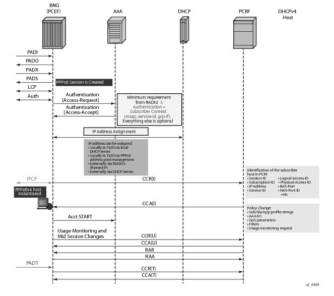
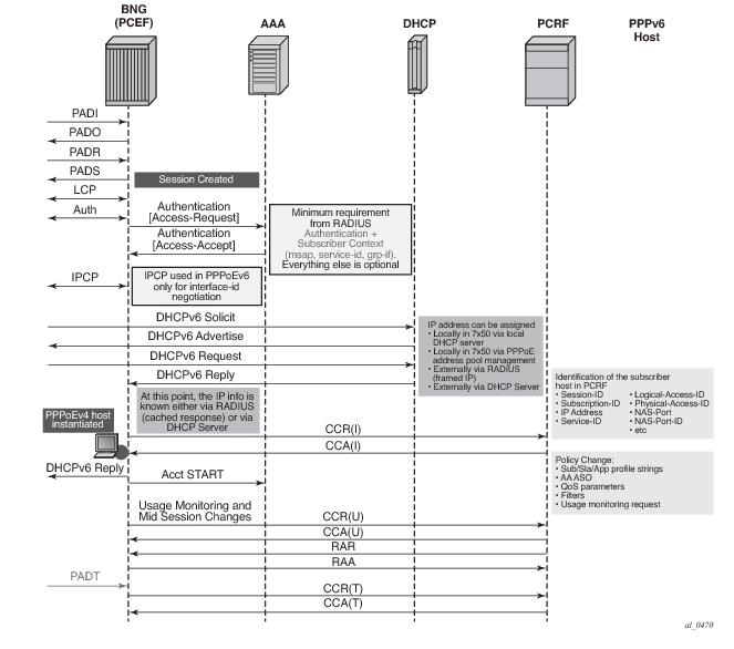
CCR-i message is sent to the PCRF once DHCP Ack is received from the DHCP server. Relaying DHCP Ack to the client in the final phase of the host instantiation process will depend on the answer from the PCRF and the configuration settings of the fallback function in case that the answer is not received.
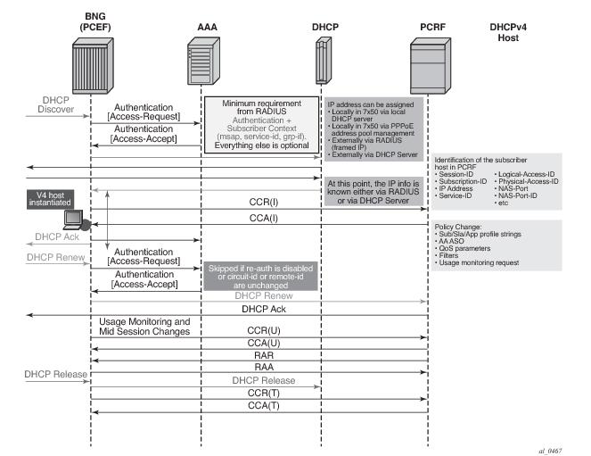
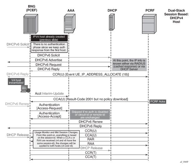
For Dual-Stack PPPoE host, the CCR-i is sent when the first IP address is assigned to the host. In the example in Figure 171, processing of the DHCPv6 Replay and CCR-u messages is performed in parallel. In other words, sending the DHCPv6 Reply message to the client will not be delayed until the response from the PCRF is received. The reason being is that the Gx session is already established (triggered by the IPv4 host in our example) and all parameters for IPv4 and IPv6 are already known as received in CCA-i. In this case, the CCR-u message is simply a notification message, informing the PCRF about the new IPv6 address/prefix being assigned to an existing client.
config
subscr-mgmt
diam-appl-plcy
on-failure
failover {enabled|disabled}
handling {continue|retry-and-terminate|terminate}
The failover configuration option (equivalent to CC-Session-Failover AVP) controls whether the secondary peer will be used in case that the primary peer is unresponsive. The unresponsiveness is determined by the timeout of the previously sent message.
The handling configuration option (equivalent to Credit-Control-Failure-Handling AVP) controls whether the subscriber will be terminated or instantiated with default parameters in case that the PCRF is unresponsive.
The CCR retransmissions are controlled by the tx-timer command under the
diameter-application-policy. Refer to the SR OS CLI reference for the description of
retransmission handling.
In the case that all peers are down (no connections are open), the handling action will determine the behavior. If the action is set to
continue, the subscriber-host will be immediately instantiated with the default-settings (provided that the defaults are available). In all other action cases, the host instantiation will be immediately terminated.
In order to resolve this situation, ESM periodically sends CCR-i for the Gx orphaned subscriber‑host until the response from PCRF is received. The CCR-i is periodically retransmitted every 60 seconds.
Some PCRFs can cope with such out-of-sync condition by periodically auditing all existing Gx sessions. For example, a probing RAR can be sent periodically for each active Gx session. The sole purpose of this probing RAR is to solicit a response from the PCEF (7x50) and provide indication on whether the corresponding Gx session is alive in 7x50 or is vanished. The ‘probing’ RAR can contain an Event-Trigger that is already applied in 7x50, or if none is applied, then the Event-Trigger can contain NO_EVENT_TRIGGER. In either case the ‘probing’ RAR will not cause any specific action to be taken in 7x50 and it is used only to solicit reply from PCRF.
To minimize the impact on performance, probing RARs are sent infrequently and thus it may take days to discover stale Gx session on PCRF. 7x50 offers a mechanism that can clear the stale session in PCRF sooner. It does this by re-playing CCR-t messages until the proper response from PCRF is received (CCA-t). The CCR-t messages will be re-played up to 24 hours. This period of 24 hours is not configurable. In case that 24hour period expires before the proper answer is received, the CCR-t is deleted and a log is generated. The log contains Gx session-id.
clear subscriber-mgmt diameter-session CCR-t-replay diameter-application-policy <gx-policy-name>.
configure
subscriber-mgmt
diameter-application-policy <pol-name>
gx
[no] report-ip-addr-event
Subscriber-host related objects are shown in Figure 173. A subscriber represents a residence or home and it is identified by Subscriber-Id string in 7x50. Subscriber in 7x50 can be comprised of multiple hosts in bridged home environment or a single host in routed home environment.
Charging-Rule-Install ::= < AVP Header: 1001 >
*[ Charging-Rule-Definition ]
*[ Charging-Rule-Name ]
*[ AVP ]
ADC-Rule-Install ::= < AVP Header: 1092 >
*[ ADC-Rule-Definition ]
*[ ADC-Rule-Name ]
*[ AVP ]
In summary, the reserved prefixes “ingr-v4:”, “ingr-v6:”, “egr-v4:”, “egr-v6:”, “in-othr-v4:”, “in-othr-v6:”, “sub-id:”, “sla-profile:”, “sub-profile:”, “inter-dest:”, “cat-map:”, “aa-um:” and “aa-functions:” have special meaning within the Charging-Rule-Name AVP in 7750.
Charging-Rule-Definition ::= < AVP Header: 1003 >
{ Charging-Rule-Name }
[ QoS-Information ]
[ Nas-Filter-Rule]
[ Alc-NAS-Filter-Rule-Shared]
*[ AVP ]
ADC-Rule-Definition ::= < AVP Header: 1094 >
{ ADC-Rule-Name }
[AA-Functions]
*[ AVP ]
Charging-Rule-Install ::= <AVP Header: 1001>
Charging-Rule-Name <AVP Header: 1005> = “sub-id:residence-1”
Charging-Rule-Name <AVP Header: 1005> = “ingr-v4:7”
Charging-Rule-Name <AVP Header: 1005> = “eggr-v6:5”
Charging-Rule-Name <AVP Header: 1005> = “Sub-Profile:prem”
Charging-Rule-Name <AVP Header: 1005> = “Sla-Profile:voip+data”
Charging-Rule-Name <AVP Header: 1005> = “Inter-Dest:vport-AN-1”
Charging-Rule-Definition <AVP Header: 1003>
Charging-Rule-Name <AVP Header: 1005> = “premium-service”
QoS-Information <AVP Header: 1016>
Alc-Queue <AVP Header; vnd ALU; 1016>
Alc-Queue-id <AVP Header; vnd ALU; 1007> = 5
Max-Requested-Bandwidth-UL <AVP Header: 516> = 10000
Max-Requested-Bandwidth-DL <AVP Header: 515> = 100000
Guaranteed-Bitrate-UL <AVP Header: 1026> = 5000
Guaranteed-Bitrate-DL <AVP Header: 1027> = 50000
Alc-Committed-Burst-Size-UL <AVP Header; vnd ALU; 1008> = 1000
Alc-Maximum-Burst-Size-UL <AVP Header; vnd ALU; 1009> = 2000
Alc-Committed-Burst-Size-DL <AVP Header; vnd ALU; 1010> = 1000
Alc-Maximum-Burst-Size-DL <AVP Header; vnd ALU; 1011> = 2000
Alc-Queue <AVP Header; vnd ALU; 1006>
Alc-Queue-id <AVP Header; vnd ALU; 1007> = 7
Max-Requested-Bandwidth-UL <AVP Header: 516> = 10000
Max-Requested-Bandwidth-DL <AVP Header: 515> = 100000
Guaranteed-Bitrate-UL <AVP Header: 1026> = 5000
Guaranteed-Bitrate-DL <AVP Header: 1027> = 50000
Alc-Committed-Burst-Size-UL <AVP Header; vnd ALU; 1008> = 1000
Alc-Maximum-Burst-Size-UL <AVP Header; vnd ALU; 1009> = 2000
Alc-Committed-Burst-Size-DL <AVP Header; vnd ALU; 1010> = 1000
Alc-Maximum-Burst-Size-DL <AVP Header; vnd ALU; 1011> = 2000
Alc-Sub-Egress-Rate-Limit <AVP Header; vnd ALU; 1016> = 10000
ADC-Rule-Install ::= <AVP Header: 1092>
ADC-Rule-Definition <AVP Header: 1094>
ADC-Rule-Name <AVP Header: 1096> = “AA-Functions:apps”
AA-Functions
AA-App-Profile-Name = “apps-prof”
AA-App-Service-Options
AA-App-Serv-Options-Name = “bitttorent”
AA-App-Serv-Options-Value = “low-prio-1mbps”
AA-App-Service-Options
AA-App-Service-Options-Name = “ftp”
AA-App-Service-Options-Value = “hi-prio”
In the following example all Gx overrides are submitted via a separate Charging-Rule-Install AVP:
Charging-Rule-Install ::= <AVP Header: 1001>
Charging-Rule-Name <AVP Header: 1005> = “sub-id:residence-1”
Charging-Rule-Install ::= <AVP Header: 1001>
Charging-Rule-Name <AVP Header: 1005> = “ingr-v4:7”
Charging-Rule-Install ::= <AVP Header: 1001>
Charging-Rule-Name <AVP Header: 1005> = “eggr-v6:5”
Charging-Rule-Install ::= <AVP Header: 1001>
Charging-Rule-Name <AVP Header: 1005> = “Sub-Profile:prem”
Charging-Rule-Install ::= <AVP Header: 1001>
Charging-Rule-Name <AVP Header: 1005> = “Sla-Profile:voip+data”
Charging-Rule-Install ::= <AVP Header: 1001>
Charging-Rule-Name <AVP Header: 1005> = “Inter-Dest:Gx-inserted-string”
Charging-Rule-Install ::= <AVP Header: 1001>
Charging-Rule-Definition <AVP Header: 1003>
Charging-Rule-Name <AVP Header: 1005> = “premium-service”
QoS-Information <AVP Header: 1016>
Alc-Queue <AVP Header; vnd ALU; 1016>
Alc-Queue-id <AVP Header; vnd ALU; 1007> = 5
Max-Requested-Bandwidth-UL <AVP Header: 516> = 10000
Max-Requested-Bandwidth-DL <AVP Header: 515> = 100000
Guaranteed-Bitrate-UL <AVP Header: 1026> = 5000
Guaranteed-Bitrate-DL <AVP Header: 1027> = 50000
Alc-Committed-Burst-Size-UL <AVP Header; vnd ALU; 1008> = 1000
Alc-Maximum-Burst-Size-UL <AVP Header; vnd ALU; 1009> = 2000
Alc-Committed-Burst-Size-DL <AVP Header; vnd ALU; 1010> = 1000
Alc-Maximum-Burst-Size-DL <AVP Header; vnd ALU; 1011> = 2000
Alc-Queue <AVP Header; vnd ALU; 1006>
Alc-Queue-id <AVP Header; vnd ALU; 1007> = 7
Max-Requested-Bandwidth-UL <AVP Header: 516> = 10000
Max-Requested-Bandwidth-DL <AVP Header: 515> = 100000
Guaranteed-Bitrate-UL <AVP Header: 1026> = 5000
Guaranteed-Bitrate-DL <AVP Header: 1027> = 50000
Alc-Committed-Burst-Size-UL <AVP Header; vnd ALU; 1008> = 1000
Alc-Maximum-Burst-Size-UL <AVP Header; vnd ALU; 1009> = 2000
Alc-Committed-Burst-Size-DL <AVP Header; vnd ALU; 1010> = 1000
Alc-Maximum-Burst-Size-DL <AVP Header; vnd ALU; 1011> = 2000
Alc-Sub-Egress-Rate-Limit <AVP Header; vnd ALU; 1016> = 10000
ADC-Rule-Install ::= <AVP Header: 1092>
ADC-Rule-Definition <AVP Header: 1094>
ADC-Rule-Name <AVP Header: 1096> = “AA-Functions:apps”
AA-Functions
AA-App-Profile-Name = “apps-prof”
AA-App-Service-Options
AA-App-Service-Options-Name = “bitttorent”
AA-App-Service-Options-Value = “low-prio-1mbps”
AA-App-Service-Options
AA-App-Service-Options-Name = “ftp”
AA-App-Service-Options-Value = “hi-prio”
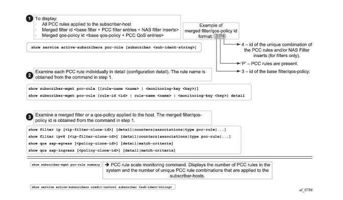
show service active-subscribers detail
========================================================================
Active Subscribers
========================================================================
------------------------------------------------------------------------
Subscriber residence-1 (prem)
-------------------------------------------------------------------------------
I. Sched. Policy : basic_policy
E. Sched. Policy : N/A E. Agg Rate Limit: 10000
I. Policer Ctrl. : N/A
E. Policer Ctrl. : N/A
Q Frame-Based Ac*: Disabled
Acct. Policy : N/A Collect Stats : Disabled
Rad. Acct. Pol. : N/A
Dupl. Acct. Pol. : N/A
ANCP Pol. : N/A
HostTrk Pol. : N/A
IGMP Policy : N/A
MLD Policy : N/A
Sub. MCAC Policy : N/A
NAT Policy : N/A
Def. Encap Offset: none Encap Offset Mode: none
Avg Frame Size : N/A
Vol stats type : full
Preference : 5
Sub. ANCP-String : "iope-left-dupl"
Sub. Int Dest Id : "Gx-inserted-string"
Igmp Rate Adj : N/A
RADIUS Rate-Limit: N/A
Oper-Rate-Limit : 10000
show service id 10 subscriber-hosts detail
=============================================================
Subscriber Host table
=============================================================
Sap Subscriber
IP Address
MAC Address PPPoE-SID Origin Fwding State
-------------------------------------------------------------
[1/1/5:6.2] iope-sub
192.168.0.11
00:00:65:06:02:01 N/A DHCP Fwding
-------------------------------------------------------------
Subscriber-interface : int1
Group-interface : g1
Sub Profile : prem
SLA Profile : voip+data
App Profile : apps-prof
Egress Q-Group : N/A
Egress Vport : N/A
Acct-Session-Id : D896FF0000001852EDFF46
Acct-Q-Inst-Session-Id: D896FF0000001952EDFF51
Address Origin : DHCP
OT HTTP Rdr IP-FltrId : N/A
OT HTTP Rdr Status : N/A
OT HTTP Rdr Fltr Src : N/A
HTTP Rdr URL Override : N/A
GTP local break-out : No
A PCC rule is addressed to a subscriber-host (single stack or dual-stack) via the Diameter session-id. However, qos-policy-related entries are applied per sla-profile instance since the qos resources are allocated per sla-instance
1. This means that all hosts sharing the same sla-profile instance will inherit the change.
In the absence of explicitly defined qos-policy for the subscriber host, the default qos-policy 1 will be in effect. In this case, PCC rules with qos related action cannot be applied.
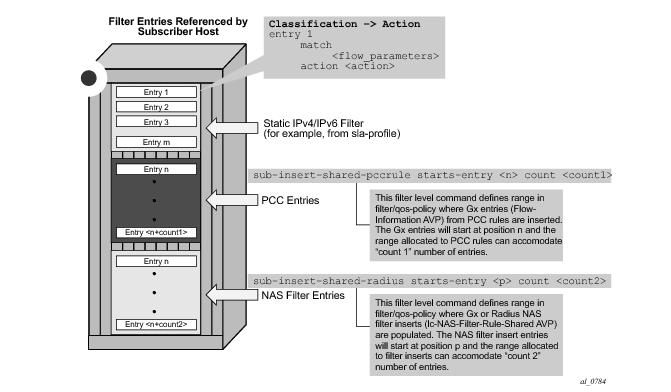
sub-insert-shared-pccrule start-entry <entry-id> count <count>
configure>filter>ip-filter>
configure>filter>ipv6-filter
configure>qos>sap-ingres>
configure>qos>sap-egress>
Policy
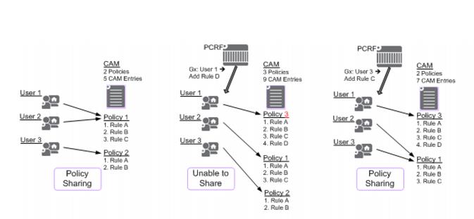
2 sharing between the subscriber hosts is depicted in
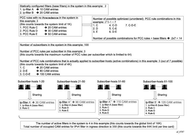
Figure 177. In order to simplify CAM scaling explanations, the examples in this section assume that one rule within the policy occupies exactly one CAM entry. For simplicity, only PCC rules are shown but in reality a subscriber-host policy consist of PCC rules together with the base qos-policy/filter.
A policy, as a set of rules, can be shared amongst the subscriber-hosts. However, when a new rule is added to one of the subscriber-host, the newly created set of rules for this host becomes unique. Hence, a new policy for the subscriber-host will be instantiated. This new policy will consume additional resources for all the old rules (clone of the old policy) along with the new rule. Figure below shows that a new policy (3) is instantiated when rule D is added to User 1, even though the rules A, B and C remain the same for Users 1 and 2. Policy 3 is a newly cloned with the same rules as Policy 1, and then Rule D is added onto it. On the other hand, when the rule C is applied to User 3, the set of rules becomes identical to the set of rules for User 2. Thus the two can start sharing rules and therefore the resources are freed.
Charging-Rule-Remove ::= < AVP Header: 1002 >
*[ Charging-Rule-Name ]
On the other hand, the PCC rules are ordered in one of the two ways
3:
Charging-Rule-Install — Directive to install the rule in 7x50
Charging-Rule-Definition — PCC rule definition created on PCRF
Charging-Rule-Name = Rule-1 — PCC rule name
Flow1 — match-criteria for flow 1
Flow2 — match-criteria for flow 2
Flow 2 — match-criteria for flow 3
Rate-limit — rate-limiting action applicable as an aggregate action for all 3 flows
Filter/QoS-policy entry order is shown in Figure 181. The order of configuration blocks (static, PCC rules or NAS filter inserts) is configurable. For example, an operator can specify that static filter entries are populated before PCC rules which are then populated before NAS filter inserts.
A PCC rule may contain multiple actions. Each action is carried in a separate, action specific AVP. The action specified in the flow-description->ipfilterrule data type is ignored. In case that the rule contains multiple instances of the same action, each with a different value, the last occurrence of the action value will be in effect.
configure
qos
sap-ingress/egress
dynamic-policer
stat-mode no-stats|minimal|offered-profile-no-cir|
offered-profile-cir|offered-total-cir|
offered-limited-capped-cir|offered-profile-capped-cir
parent <arbiter-name> [weight <weight-level>] [level <level>
mbs <size> [bytes | kilobytes]
cbs <size> [bytes | kilobytes]
packet-byte-offset {add <add-bytes> | subtract <sub-bytes>}
range start-entry <entry-id> count <count>
Charging-Rule-Install ::= <AVP Header: 1001>
Charging-Rule-Definition <AVP Header: 1003>
Charging-Rule-Name <AVP Header: 1005>
QoS-Information <AVP Header: 1016>
Max-Requested-Bandwidth-UL <AVP Header: 516> [bps] 3GPP 29.214 §5.3.15
Max-Requested-Bandwidth-DL <AVP Header: 515> [bps] 3GPP 29.214 §5.3.14
Guaranteed-Bitrate-UL <AVP Header: 1026> [bps] 3GPP 29.214 §5.3.26
Guaranteed-Bitrate-DL <AVP Header: 1027> [bps] 3GPP 29.214 §5.3.25
Once traffic is processed by the dynamic policers on ingress, the traffic will flow through the policer-output-queues shared queues. Traffic through dynamic policers will always bypass subscriber queues or policers on
ingress that are statically configured in the base qos-policy.
Similar behavior is exhibited when static policers are configured on egress. Traffic outputting dynamic policer is never mapped to another static policer. Instead, such traffic will be mapped to the corresponding shared queue in a queue-group. By default, this queue-group is the policer-output-queue group. However, the selection of the queue-group is configurable.
In contrast to the above, traffic processed by dynamic policers can be fed into statically configured subscriber (local) queues on egress. Dynamic policers and subscriber queues are tied through the forwarding-class.
Dynamic policer
4 statistics are not reported in RADIUS-based accounting. On egress, this will have no effect on volume counters in RADIUS-based accounting, since the dynamic policers are normally fed into local queues whose statistics are reported in RADIUS-based accounting. However, on ingress, the dynamic policers are always fed into the queue-group queues which are excluded from RADIUS based accounting. The consequence is that the ingress RADIUS-based accounting will lack statistics for the traffic that is flowing via dynamic policers.
queue 4 create //Not counted since policer 2 is feeding it
exit
policer 2 create
exit
fc be create
queue 4 //Not counted
exit
fc l1 create
queue 4 //Not counted
exit
fc ef create
policer 2 queue 4
exit
In this case, the configured entry range for PCC rules must precede the static entry (match criteria) in which the original forwarding-class is configured. The insertion point (entry) is controlled via configuration:
sub-insert-shared-pccrule start-entry <entry-id> count <count> command under the qos-policy.
Charging-Rule-Install <AVP Header: 1001>
Charging-Rule-Definition <AVP Header: 1003>
Charging-Rule-Name <AVP Header: 1005>
Alc-Next-Hop :: <AVP Header: 1023>
Alc-Next-Hop-IP <AVP Header: 1024>
Alc-V4-Next-Hop-Service-id <AVP Header: 1025>
Alc-V6-Next-Hop-Service-id <AVP Header: 1026>
Redirect-Information < AVP Header: 1085 >
Redirect-Support < AVP Header: 1086 >
Redirect-Address-Type < AVP Header: 433 >
Redirect-Server-Address < AVP Header: 435 >
The gate function is analogous to the forward | drop action within IP filters in CLI.
The gating action enabled (2) is the default action and it must be accompanied by at least one other action. In other words, the gating action
enable cannot be the only action in the PCC rule. Otherwise the PCC rule is treated as it would not have any action at all and as such it will be rejected.
In case that the gating action is set to disable (3), all other actions within the same rule will lose their meaning since the packet will be dropped. In effect, the
disabled directive will disable the flow of classified traffic through the system. Note that this is not the same as
disabling the rule in a sense that the flow of packets would be permitted through the 7x50 although with no actions applied.
Charging-Rule-Definition ::= < AVP Header: 1003 >
{ Charging-Rule-Name }
*[ Flow-Information ]
[ Flow-Status ]
[ QoS-Information ]
[ Precedence ]
*[ Flows ]
[ Monitoring-Key]
[ Redirect-Information ]
*[ AVP ]
<CC-Answer> ::= < Diameter Header: 272, PXY >
< Session-Id >
{ Auth-Application-Id }
{ Origin-Host }
{ Origin-Realm }
[ Result-Code ]
[ Experimental-Result ]
{ CC-Request-Type }
{ CC-Request-Number }
*[ Supported-Features ]
*[ Event-Trigger ]
[ Origin-State-Id ]
Charging-Rule-Install ::= <AVP Header: 1001> — host instantiation
Charging-Rule-Name = “ingr-v4:7”
Charging-Rule-Name = “eggr-v6:5”
Charging-Rule-Name = “Sub-Profile:prem”
Charging-Rule-Name = “Sla-Profile:voip+data”
Charging-Rule-Name = “Inter-Dest:vport-AN-1”
Charging-Rule-Install — service instantiation
Charging-Rule-Definition
Charging-Rule-Name = “service-1” — should be able to remove the rule by name later on
Flow-Information — traffic flow definition
Flow-Description = “permit in 6(TCP) from any to ip 10.10.10.10/32 40000-40010"
ToS-Traffic-Class = 00101000 11111100] — DSCP definition (value mask). In case of the DSCP, Flow-Direction (1080) AVP must be included.
Flow-Direction = UPSTREAM — traffic flow direction
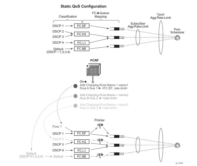
QoS-Information <AVP Header: 1016>
Max-Requested-Bandwidth-UL = 10000000 — UPSTREAM rate definition (not downstream, since the traffic flow direction is IN)
QoS-Class-Identifier = 3 — EF forwarding class; in general one of 8 forwarding-classes (FC) in 7x50 (be|l2|af|l1|h2|ef|h1|nc). This is used for re-prioritization of the traffic.
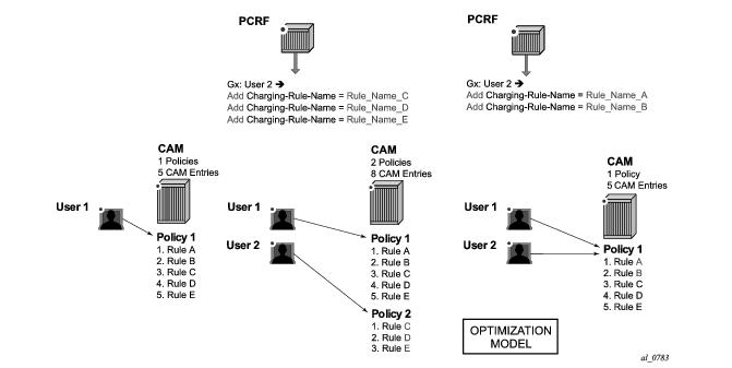
The Figure 184 depicts an example relevant to capacity planning, with focus on understanding the scaling limits when it comes to the number of PCC rules and their mutual combinations when they are applied to the subscriber hosts.
On the other hand, the entries in the Alc-NAS-Filter-Rule-Shared AVP are processed as received without any modifications. This means that such entries can be shared with all the hosts that have the same Alc-NAS-Filter-Rule-Shared applied.
Charging-Rule-Install ::= <AVP Header: 1001>
Charging-Rule-Definition <AVP Header: 1003>
Charging-Rule-Name <AVP Header: 1005> = “allow-all”
Alc-NAS-Filter-Rule-Shared <AVP Header: 158> = "permit in ip from any to any "ASCII NUL" permit out ip from any to any"
Charging-Rule-Install ::= <AVP Header: 1001>
Charging-Rule-Name <AVP Header: 1005> = “Sub-Profile:prem”
Charging-Rule-Name <AVP Header: 1005> = “Spa-Profile:voip+data”
Since the Charging-Rule-Name AVP has the M-bit set, the whole message will fail and an error will be reported. No rules within this Gx message will be installed (not even the valid ones, in this case this would be the
Charging-Rule-Name = “
Sub-Profile:prem”). Note that if the M-bit was clear in the
Charging-Rule-Name AVP, the erroneous AVP would be simply ignored and we would proceed with installation of the remaining, ‘correctly formatted’ rules.
[ Error-Message ] — “Invalid value spa-profile:voip+data”
Charging-Rule-Report ::= < AVP Header: 1018 >
*[ Charging-Rule-Name ] — Spa-Profile:voip+data
[ PCC-Rule-Status ] — INACTIVE (1)
[ Rule-Failure-Code ] — GW/PCEF_MALFUNCTION (4)
Charging-Rule-Report ::= < AVP Header: 1018 >
*[ Charging-Rule-Name ] — Sub-Profile:prem
[ PCC-Rule-Status ] — INACTIVE (1)
[ Rule-Failure-Code ] — GW/PCEF_MALFUNCTION (4)
Failed-AVP ::= < AVP Header: 279 >
Charging-Rule-Name = Spa-Profile:voip+data
Failed-AVP ::= < AVP Header: 279 >
Charging-Rule-Name = Spa-Profile:voip+data
Result-Code ::= < AVP Header: 268 > = DIAMETER_INVALID_AVP_VALUE (5004)
Charging-Rule-Install ::= <AVP Header: 1001>
Charging-Rule-Name <AVP Header: 1005> = “Sub-Profile:prem”
Charging-Rule-Name <AVP Header: 1005> = “Sla-Profile:unknown”
[ Error-Message ] — “sla-profile ‘unknown’ lookup failed”
Charging-Rule-Report ::= < AVP Header: 1018 >
*[ Charging-Rule-Name ] — Sla-Profile:unknown
[ PCC-Rule-Status ] — INACTIVE (1)
[ Rule-Failure-Code ] — GW/PCEF_MALFUNCTION (4)
Charging-Rule-Report ::= < AVP Header: 1018 >
*[ Charging-Rule-Name ] — Sub-Profile:prem
[ PCC-Rule-Status ] — INACTIVE (1)
[ Rule-Failure-Code ] — GW/PCEF_MALFUNCTION (4)
ADC-Rule-Report ::= < AVP Header: 1097 >
*[ ADC-Rule-Name ]
[ PCC-Rule-Status ]
[ Rule-Failure-Code ]
*[ AVP ]
Table 29 summarizes Gx failure reporting in 7750.
*A:7750>config>subscr-mgmt>cat-map# info
----------------------------------------------
activity-threshold 1
credit-exhaust-threshold 50
category "queue1" create
queue 1 ingress-egress
exit
category "queue3-5" create
queue 3 ingress-egress
queue 5 ingress-egress
exit
category "rest-queues" create
queue 2 egress-only
queue 4 egress-only
queue 6 egress-only
queue 7 egress-only
queue 8 egress-only
exit
----------------------------------------------
Usage-Monitoring-Information::= < AVP Header: 1067 >
[ Monitoring-Key ]
0,2 [ Granted-Service-Unit ]
0,2 [ Used-Service-Unit ]
[ Usage-Monitoring-Level ]
[ Usage-Monitoring-Report ]
[ Usage-Monitoring-Support ]
Charging-Rule-Definition ::= < AVP Header: 1003 >
{ Charging-Rule-Name }
*[ Flow-Information ]
[ Flow-Status ]
[ QoS-Information ]
[ Precedence ]
[ Monitoring-Key]
*[ AVP ]
Usage-Monitoring-Information
Monitoring-Key = “any-string”
Granted-Service-Unit
CC-Input-Octets = 1000000
CC-Output-Octets = 1000000
Usage-Monitoring-Level = session_level(0)
Event-Trigger = USAGE_REPORT
Usage-Monitoring-Information
Monitoring-Key = “any-string”
Used-Service-Unit
CC-Input-Octets = 1000000
CC-Output-Octets = 1000000
Usage-Monitoring-Information
Monitoring-Key = “any-string”
Granted-Service-Unit
CC-Input-Octets = 1000000
CC-Output-Octets = 1000000
Usage-Monitoring-Level = session_level(0)
*A:7750>config>subscr-mgmt>cat-map# info
----------------------------------------------
activity-threshold 1
credit-exhaust-threshold 50
category "queue1" create
queue 1 ingress-egress
exit
category "queue3-5" create
queue 3 ingress-egress
queue 5 ingress-egress
exit
category "rest-queues" create
queue 2 egress-only
queue 4 egress-only
queue 6 egress-only
queue 7 egress-only
queue 8 egress-only
exit
Charging-Rule-Install
Charging-Rule-Name = Cat-Map:cat1 — cat-map rule install
Usage-Monitoring-Information
Monitoring-Key = “queue-1”
Granted-Service-Unit
CC-Input-Octets = 1000000
CC-Output-Octets = 1000000
Usage-Monitoring-Level = PCC_RULE_LEVEL (1)
Usage-Monitoring-Information
Monitoring-Key = “queue-3-5”
Granted-Service-Unit
CC-Input-Octets = 2000000
CC-Output-Octets = 2000000
Usage-Monitoring-Level = PCC_RULE_LEVEL (1)
Event-Trigger = USAGE_REPORT
Usage-Monitoring-Information
Monitoring-Key = “queue-1”
Used-Service-Unit
CC-Input-Octets = 1000000
CC-Output-Octets = 1000000
Usage-Monitoring-Information
Monitoring-Key = “queue-3-5”
Used-Service-Unit
CC-Input-Octets = 2000000
CC-Output-Octets = 2000000
Usage-Monitoring-Information
Monitoring-Key = “queue-1”
Granted-Service-Unit
CC-Input-Octets = 1000000
CC-Output-Octets = 1000000
Usage-Monitoring-Level = PCC_RULE_LEVEL (1)
Usage-Monitoring-Information
Monitoring-Key = “queue-3-5”
Granted-Service-Unit
CC-Input-Octets = 2000000
CC-Output-Octets = 2000000
Usage-Monitoring-Level = PCC_RULE_LEVEL (1)
Table 30 lists the supported Diameter NASREQ messages. Vendor-specific AVP's are shown as: v-<vendor-id>-<AVP id>.
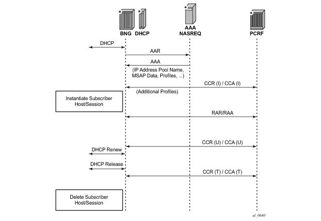
Figure 185 shows a sample call flow for a subscriber using Diameter NASREQ for authentication and Diameter Gx for policy management.
Table 31 lists the authorization AVPs that are accepted in a Diameter NASREQ AA-Answer message. Vendor-specific AVPs are shown in the table as: v-<vendor-id>-<AVP-id>.
configure
aaa
diameter-peer-policy "diameter-peer-policy-1" create
description "Diameter NASREQ peer policy"
applications nasreq
origin-host "bng@alcatel-lucent.com"
origin-realm "alcatel-lucent.com"
peer "peer-1" create
address 172.16.3.1
destination-realm "myDSCRealm.com"
no shutdown
exit
exit
configure
subscriber-mgmt
diameter-application-policy "diameter-nasreq-policy-1" create
description "Diameter NASREQ application policy"
application nasreq
diameter-peer-policy "diameter-peer-policy-1"
nasreq
user-name-format mac
include-avp
circuit-id
nas-port-id
nas-port-type
remote-id
exit
exit
exit
(Note: A Diameter authentication policy cannot be configured simultaneously with a RADIUS authentication policy on the same group-interface or capture SAP, nor for the same host in a local user database.)
configure
service
vpls 10 customer 1 create
sap 1/1/4:*.* capture-sap create
---snip---
diameter-auth-policy "diameter-nasreq-policy-1"
ies 1000 customer 1 create
subscriber-interface "sub-int-1" create
---snip---
group-interface "group-int-1-1" create
---snip---
diameter-auth-policy "diameter-nasreq-policy-1"
vprn 2000 customer 1 create
subscriber-interface "sub-int-1" create
---snip---
group-interface "group-int-1-1" create
---snip---
diameter-auth-policy "diameter-nasreq-policy-1"
configure
subscriber-mgmt
local-user-db "ludb-1" create
ipoe
host "ipoe-host-1" create
---snip---
diameter-auth-policy "diameter-nasreq-policy-1"
ppp
host "ppp-host-1" create
diameter-auth-policy "diameter-nasreq-policy-1"
configure
subscriber-mgmt
diameter-application-policy "diameter-nasreq-policy-1" create
on-failure failover enabled handling continue
configure
python
python-policy "py-policy-nasreq-1" create
diameter aar direction egress script "NasreqAar"
diameter aaa direction ingress script "NasreqAaa"
configure
aaa
diameter-peer-policy "diameter-peer-policy-1" create
---snip---
python-policy "py-policy-nasreq-1"
|
•
|
Diameter Peer Level Redundancy: A Diameter client in 7x50 supports up to five open peers, two of which (primary and secondary) can actively participate in Diameter transactions. The purpose of the secondary peer is to protect the primary peer, should the primary peer experience problems.
|
|
•
|
Diameter Multi-Chassis Redundancy: Diameter sessions are synchronized on the application level (via ESM in case of Gx and NASREQ) between two redundant 7x50 nodes. Only one of the 7750 SRs opens up a peering connection on behalf of the redundant 7750 SR pair towards DRA/PCRF.
|
|
•
|
High Availability (HA): This refers to control plane redundancy with dual Control Plane Modules (CPMs) in a single chassis configuration. Diameter transactions are fully synchronized between CPMs and the peering connection towards DRA/PCRF remains uninterrupted in case that one of the control plane modules fails.
|
Once the peer in the Diameter policy (maximum five peers per policy) is administratively enabled (no-shutdown), the 7x50 starts connecting to it. If the establishment of the TCP connection fails, the 7x50 periodically retries to connect.
If creation of the TCP connection succeeds, the peer is placed in the peer table, and in that table the “preference” defines the
current usability of the peers. All administratively enabled peers that are in the open state have keepalives (DWR/DWA) enabled to check the liveliness of the connection, but only the two open peers with the highest preference are considered as primary and secondary. In this fashion, the application messages (for example, DCCA or Gx) are sent only to the primary and/or the secondary peer.
So in essence, a revertive mode is used for the peer recovery, where the sessions are reverted back to the peer on which the session was originally setup, as long as this peer is one of the two active peers (primary and secondary).
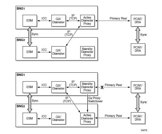
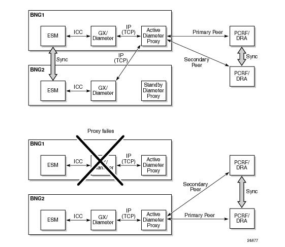
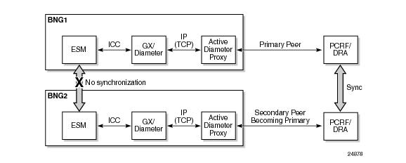
Figure 186 illustrates the basic concept for Diameter Multi-Chassis Redundancy for a Gx application. The model shows two 7750 SRs (BNGs). Each BNG contains an ESM module and a Gx/Diameter module which have a peering connection to the active Diameter proxy module. The peering connections are IP connections. Both nodes communicate with the PCRF/DRA through the active Diameter proxy which maintains a peering connection with the PCRF/DRA.

|
1.
|
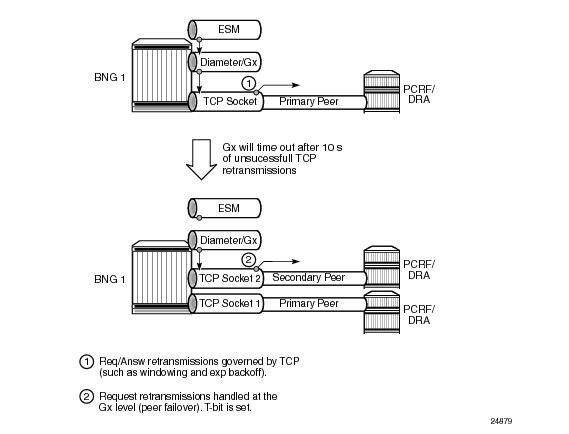
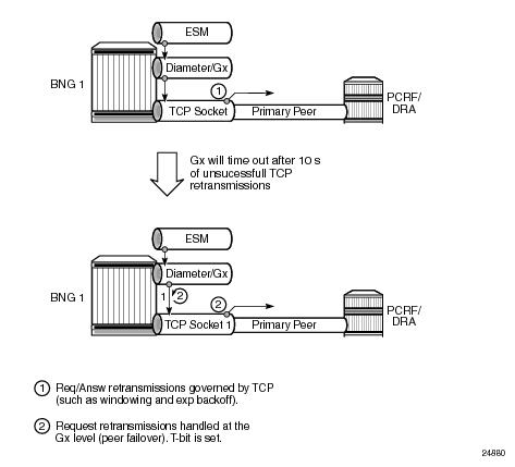
The first level of retransmissions occurs at the TCP level. The Gx message is handed over to the TCP socket Base Diameter module. TCP tries to deliver this message in a connection‑oriented (reliable) fashion. If a TCP ACK for the transmitted message is not received, the message, in the most common case, is retransmitted in intervals of 1.5 s, 3 s,
6 s, up to 64 s. After 10 s of trying to retransmit the message to the same peer at the TCP level, the Base Diameter tries to retransmit (configuration dependent) the message to the next TCP socket (secondary peer). The assumption is that the primary peer is unavailable (busy, failed, or the network path to it is broken) after 10 s of trying. The TCP retransmissions are peer oriented and very localized (to the particular TCP connection on the particular BNG node). In the case of a network failure, TCP retransmissions cannot re-route the traffic to an alternate destination. As such, they cannot protect against the peer (PCRF) failure or the BNG node failure. They can, however, indirectly provide a clue that something is happening at the peer level, so that the upper layers can take adequate actions. Note that watchdogs are also used to detect peer failure and they can provide faster detection of the peer failure (after 2 s).
|
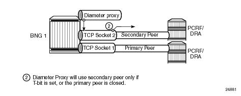
When the request message is retransmitted by the Diameter application (due to the Tx timer timeout, primary peer failure - DWR timeout, or receipt of the answer message with E-bit set), the content of the message stays the same, including the CC-Request numbers but the T-bit in the Diameter header is set. The T-bit indicates to the PCRF that the message is retransmitted (mostly used for accounting purposes so that the counting records are not duplicated). It also signals to the Diameter proxy that the message rerouting to the secondary peer should be performed.
Table 32 summarizes the differences between the regular Diameter client and the Diameter proxy.