For feedback and comments:
documentation.feedback@alcatel-lucent.com

Table of Contents Previous Next PDF


L2TP
In This Chapter
This chapter provides information about using L2TP, including theory, supported features and configuration process overview.
Topics in this chapter include:
L2TP
 
Terminology
Peer — A run-time object that is defined by a ip-address/port combination. Multiple tunnels can be terminated on the same peer. The list of peers can be obtained using the show router l2tp peer command.
 
LAC DF Bit
The LAC DF bit is configurable, but by default, it sends all L2TP packets with the DF bit set to 1. Clearing the DF bit will allow downstream routers to fragment the L2TP packets. The LAC itself will not fragment L2TP packets. L2TP packets that have a larger MTU size than what the LAC egress ports allows are dropped. The DF bit can also be configured via RADIUS attribute Alc-Tunnel-DF-bit.
 
 
Handling L2TP Tunnel/Session Initialization Failures
 
L2TP Tunnel/Session Initialization Failover Mechanisms on LAC
In deployment scenarios with multiple LNS nodes, a list of those LNS nodes can be presented to the LAC during the L2TP session instantiation process (either through CLI or RADIUS). An example of this would be a RADIUS Accept message with a list of tunnel peers:
tunnel.com Auth-Type := Local, Password == "tunnel1"
Tunnel-Type:1 += L2TP,
       	Tunnel-Medium-Type:1 += IP,
       	Tunnel-Client-Auth-Id:1 += lns_tun,
       	Tunnel-Assignment-Id:1 += 1,
   	Tunnel-Client-Endpoint:1 += 10.0.0.1,
   	Tunnel-Server-Endpoint:1 += 10.0.0.2,
       	Tunnel-Password:1 += TUNNELPASS,
 
		Tunnel-Type:2 += L2TP,
  	Tunnel-Medium-Type:2 += IP,
 		Tunnel-Client-Auth-Id:2 += lns_tun,
   	Tunnel-Assignment-Id:2 += 2, 
       	Tunnel-Client-Endpoint:2 += 10.0.0.1,
       	Tunnel-Server-Endpoint:2 += 10.0.0.3,
       	Tunnel-Password:2 += TUNNELPASS,
 
			Tunnel-Type:3 += L2TP,
       	Tunnel-Medium-Type:3 += IP,
       	Tunnel-Client-Auth-Id:3 += lns_tun,
       	Tunnel-Assignment-Id:3 += 3, 
       	Tunnel-Client-Endpoint:3 += 10.0.0.1,
       	Tunnel-Server-Endpoint:3 += 10.0.0.4,
       	Tunnel-Password:3 += TUNNELPASS,
			Tunnel-Type:4 += L2TP,
 
       	Tunnel-Medium-Type:4 += IP,
       	Tunnel-Client-Auth-Id:4 += lns_tun,
       	Tunnel-Assignment-Id:4 += 4, 
       	Tunnel-Client-Endpoint:4 += 10.0.0.1,
       	Tunnel-Server-Endpoint:4 += 10.0.0.5,
       	Tunnel-Password:4 += TUNNELPASS
 
In case that the tunnel or the session establishment attempt fails for any reason, a search for additional operational facilities (tunnels or peers) will be made in order to complete the establishment of the tunnel/session that failed in the previous attempt. Moreover, sometimes it is required to go beyond this automatic search for the new facilities and place the tunnel/peer in question into a blacklist. A tunnel timeout will always force the corresponding peer and the tunnel into the blacklist. In addition, a tunnel can be forced into the blacklist by certain explicit error codes (CDN, and Stop-CCN) during the tunnel/session initialization phase. A peer is never forced on a blacklist as a consequence of explicit Result-Code sent by LNS.
Blacklisted peers and tunnels are not eligible to serve new incoming L2TP session until they are removed from the blacklist. The exception case is when all tunnel specs evaluate into a blacklisted item. In this case a blacklisted item (tunnel) will be tried.
 
Peer Blacklist
A peer is always placed into the blacklist if:
A tunnel timeout will occur if an acknowledgement is not received after max-retries-established (on an established tunnel) or max-retries-not-established (for the tunnel in the process of being established) retries.
Although there is no configuration option that would control whether a peer can or cannot be blacklisted (it is always blacklisted on tunnel timeout), the amount of time that a peer remains in the blacklist is configurable within the tunnel-selection-blacklist CLI node.
 
Tunnel Blacklists
A tunnel spec (that evaluates into a tunnel) is temporary unusable in case that corresponding peer or the tunnel is blacklisted. The following events will trigger placement of the tunnel into the blacklist:
1.
Transmit CDN when no session can be allocated
Audit not yet complete
No result code available
Tunnel is not usable (for example lns-group is not configure on LNS)
2.
Error messages identified by the received Result-Codes can be interpreted as the inability of the LNS to accept additional L2TP sessions within the tunnel (for example due to resource depletion) or to accept additional new tunnels.
The following statements further describe behavior related to the placement of tunnels into the blacklist:
In case that the end-point is not in the routing table (unreachable via routing), the end-point is marked as permanently unavailable (removed from the L2TP process). Such end-point will never be blacklisted.
 
Tunnel Timeout Due to the Peer IP Address Change
In case that the peer address is changed mid-session (for example, from configured IP@ 1.1.1.1 to the new IP@ 2.2.2.2), and then subsequently the tunnel times-out, the new peer 2.2.2.2 would be placed in the blacklist by default. The tunnel itself would not be placed in the blacklist since it is originally tied to a different peer address that it is not in the blacklist. As such it would be eligible for selection the next time a new session request for it arrives. To block selection of this failed tunnel, we can optionally (by configuration) force it into the blacklist.
This behavior can be enabled with the following CLI:
configure router l2tp
configure service vprn <id> l2tp
	tunnel-selection-blacklist
		add-tunnel on <reason> [<reason>...(upto 7 max)]
<reason> : cdn-err-code|cdn-inv-dest|cdn-tmp-no-facilities|cdn-perm-no-facilities|tx-cdn-not-established-in-time|stop-ccn-err-code|stop-ccn-other|addr-change-timeout
Tunnel Selection Mechanism
Once the L2TP tunnel failover is triggered (timeout or specific L2TPsession/tunnel setup error message), a new tunnel spec in the list of available tunnel specs will be selected. This tunnel selection mechanism can be controlled via CLI so that the new tunnel-spec is selected from the next preference level. Alternatively the tunnel selection mechanism can be set to a mode where once all the possibilities within the same preference are exhausted, tunnel specs on a higher preference level will be tried.
configure router l2tp
configure service vprn <id> l2tp
	next-attempt same-preference-level | next-preference-level
In case that ALL tunnels on a given preference levels are blacklisted, then the behavior will depend on the configuration option as per the following:
Tunnel Probing
Tunnel probing refers to the mechanism where the blacklisted tunnel or an end-point can be selected to serve only a single L2TP session initialization request. Only in case that this single L2TP session is successfully established over the selected tunnel, the tunnel can be removed from the blacklist and consequently can serve new L2TP sessions. The tunnel is eligible for probing once its preconfigured time in the blacklist has expired.
This behavior will ensure that the new session initialization requests are not buffered while waiting for the tunnel to transition into operational state. Buffering would incur session setup delay and in the worst case it would cause session timeout in case that the L2TP tunnel cannot be established.
Without tunnel probing enabled, tunnels will be automatically removed from the blacklist upon the expiry of the preconfigured timer. New consecutive L2TP session initialization requests for such tunnels will always be buffered.
 
Controlling the Size of Blacklist
The size of the blacklist and the time that an item remains ineligible for selection within the blacklist, is configurable.
configure router l2tp
configure service vprn <id> l2tp	tunnel-selection-blacklist
		max-time		 1..60 (minutes) 
		max-list-length unlimited | 1..65535
 
 
Displaying the Content of a Blacklist
The content of a blacklist along with the remaining time that each entity is confined to the blacklist can be displayed with the following command:
show router <id> l2tp peer blacklisted|not-blacklisted|selectable 
Example:
show router l2tp peer 10.100.0.2
===============================================================================
Peer IP: 10.100.0.2
===============================================================================
Roles capab/actual: LAC LNS /LAC  -     Draining          : false
Tunnels           : 1                   Tunnels Active    : 0
Sessions          : 1                   Sessions Active   : 0
Reachability      : blacklisted         Time Unreachable  : 01/31/2013 08:55:06
Time Blacklisted  : 01/31/2013 08:55:06 Remaining (s)     : 34
===============================================================================
Conn ID                      Loc-Tu-ID Rem-Tu-ID State              Ses Active
  Group                                                             Ses Total
    Assignment
-------------------------------------------------------------------------------
977207296                    14911     0         closed             0
  base_lac_base_lns                                                 1
    t1
-------------------------------------------------------------------------------
No. of tunnels: 1
===============================================================================
 
 
show router l2tp tunnel detail
===============================================================================
L2TP Tunnel Status
===============================================================================
 
Connection ID: 831782912
State        : closedByPeer
IP           : 10.0.0.1
Peer IP      : 10.100.0.2
Tx dst-IP    : 10.100.0.2
Rx src-IP    : 10.100.0.2
Name         : lac
Remote Name  :
Assignment ID: t1
Group Name   : base_lac_base_lns
Acct. Policy : l2tp-base
Error Message: N/A
 
                                        Remote Conn ID    : 4294901760
Tunnel ID         : 12692               Remote Tunnel ID  : 65535
UDP Port          : 1701                Remote UDP Port   : 1701
Preference        : 50                  Receive Window    : 64
Hello Interval (s): 300
Idle TO (s)       : 5                   Destruct TO (s)   : 60
Max Retr Estab    : 5                   Max Retr Not Estab: 5
Session Limit     : 32767               AVP Hiding        : sensitive
Transport Type    : udpIp               Challenge         : never
Time Started      : 01/31/2013 08:56:58 Time Idle         : 01/31/2013 08:56:58
Time Established  : N/A                 Time Closed       : 01/31/2013 08:56:58
Stop CCN Result   : reqShutDown         General Error     : noError
Blacklist-state   : blacklisted
Blacklist Time    : 01/31/2013 08:56:58 Remaining (s)     : 49
-------------------------------------------------------------------------------
No. of tunnels: 1
===============================================================================
 
Generating Trap when the Blacklist is Full
A log is generated when the blacklist reaches its max limit of items. The log event is tmnxL2tpTunnelSelectionBlacklistFull.
 
Premature Removal of Blacklisted Entries
In case that the total number of supported tunnels and peers in blacklist and in the LAC in general has reached its maximum, then on the new session initialization request, the oldest tunnel entry in the blacklist will be removed from the blacklist irrespective of whether their blacklist max-time has expired or not.
 
Manual Purging of Entities within the Blacklist
The items can be manually purged from the blacklist using the following commands .
clear router <id> l2tp tunnel-selection-blacklist
clear router <id> l2tp peer <ip-address> [udp-port <port>] tunnel-selection-blacklist
clear router <id> l2tp group <tunnel-group-name> [tunnel <tunnel-name>] tunnel-selection-blacklist
clear router <id> l2tp tunnel <connection-id> tunnel-selection-blacklist
 
Stateless Address Auto-configuration (SLAAC) Management
 
SLAAC Principles
In a Triple Play network, client devices can use SLAAC to dynamically obtain their IP address and other network configuration information.
1.
2.
3.
 
Configuration Overview
The trigger for creating a SLAAC host is AAC host can choose to authenticate through Radius, LUDB, or bypass authentication. Address assignment can be assigned statically or dynamically. Static prefix assignment is accomplished through Radius or LUDB. Dynamic prefix assignment requires the use of the local-address-server (reusing the local DHCPv6 server), and a pool name returned from RADIUS or LUDB. The DHCPv6 server for SLAAC is used for address management only, there are no lease state associated with SLAAC users. The DHCPv6 server can be shared with regular DHCPv6 users as well.
 
Router-solicit trigger
The following example shows a router-solicit (RS) triggered configuration.
*A:eng-BNG-2>config>service>vprn>sub-if>grp-if>ipv6# info 
----------------------------------------------
                        router-solicit
                            no shutdown
                        exit
 
To add authentication to the above configuration, there are two options.
For radius authentication, similar to DHCP and PPP authentication, add a radius-policy under group-interface
 
 
For LUDB, add the following to the router-solicit configuration.
*A:eng-BNG-2>config>service>vprn>sub-if>grp-if>ipv6# info 
----------------------------------------------
                        router-solicit
                            user-db "slaac-users"
                            no shutdown
                        exit
 
 
SLAAC Address Assignment
After a RS is received to trigger the creation of a SLAAC host, address assignment can be provided statically or dynamically.
 
Static SLAAC Prefix Assignment
If using RADIUS, the attribute “framed-ipv6-prefix” VSA is used. The attribute must be a /64 prefix.
*A:eng-BNG-2>config>subscr-mgmt>loc-user-db>ipoe>host# info 
----------------------------------------------
                    ipv6-slaac-prefix 2001::/64
 
 
Dynamic SLAAC Prefix Assignment
SLAAC prefix can be dynamically assigned to a user at real time. Prefixes are assignment through the local DHCPv6 pool. Therefore a DHCPv6 pool must be defined first. The following displays an example configuration.
*A:eng-BNG-2>config>service>vprn>dhcp6# info
----------------------------------------------
       local-dhcp-server "dhcp6-server" create
              use-pool-from-client
              pool "pool-01" create
                     prefix 2001::/32 wan-host create
                     exit
              exit
        exit
To associate the dhcpv6 server for SLAAC address assignment, the following configuration is used. Notice the server name configured under local-address-assignment “dhcp6-server” matches the name configured under dhcp6 pool.
*A:eng-BNG-2>config>service>vprn>sub-if>grp-if# info 
----------------------------------------------
                    local-address-assignment
                        ipv6
                            client-application ppp-slaac ipoe-slaac
                            server "dhcp6-server"
                        exit
                        no shutdown
                    exit
 
In order to specify the pool to be used for SLAAC prefix assignment, the pool name can either be returned from LUDB or Radius.
If using Radius, the attribute “Alc-slaac-ipv6-pool” is used.
If using LUDB, the following configuration is used.
*A:eng-BNG-2>config>subscr-mgmt>loc-user-db>ipoe>host# info 
----------------------------------------------
                    ipv6-slaac-prefix-pool "pool-01"
 
In this example, the pool named “pool-01” provisioned in the LUDB or returned from Radius will match the pool name configured in the dhcp6 server. A prefix from the 2001::/32 pool will be assigned to the SLAAC subscribers.
 
CDN Result Code Overwrite
When the number of L2TP sessions reaches the configured maximum value, the LNS sends an out-of-resource Result Code (4 or 5) in a CDN (Call-Disconnect-Notify) message to the LAC. This would trigger the LAC to fail over to another LNS that has the resources available. Similarly, when the tunnel is not usable due to the invalid destination CDN error, the Result-Code 6 will be sent from the LNS.
Certain third-party LAC implementations will trigger tunnel failover only when they receive Result Code 2 in CDN messages (and not 4,5 or 6). In order to support those scenarios, the LNS in 7x50 can overwrite result codes 4, 5 and 6 with result code 2 just before they are sent to the LAC. Result Codes can be overwritten only during the L2TP session initialization phase. These codes have the following meanings and are described in RFC 2661, 4.4.2:
This functionality will be enabled on LNS via the following CLI hierarchy:
configure router l2tp
configure service vprn <id> l2tp
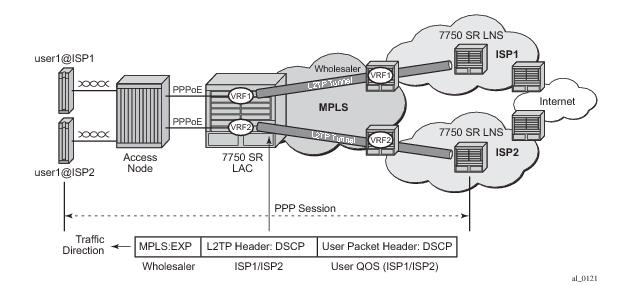
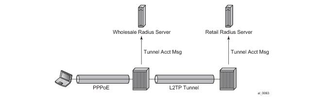
   replace-result-code {cdn-tmp-no-facilities | cdn-prem-no-facilities | cdn-inv-dest}
    no replace-result-code
 
L2TP LAC VPRN
Layer 2 Tunneling Protocol (L2TP) allows for PPP sessions to be carried over an IP network.
Each L2TP session transports PPP frames, irrespective of link-layer encapsulation, allows the LNS to terminate PPP sessions that were either PPPoE or PPPoA. L2TP is carried over IPv4 packets in UDP datagrams (default port 1701).
If session data is not reliably delivered, that is, if there is a packet loss, there is no retransmission, a sequence numbers is used within each L2TP session to identify packet loss and re-ordering.
L2TP is comprised of the following concepts:
L2TP tunnels provide an IP transport for PPP frames between LAC and LNS. In some existing networks, BGP/MLPS VPNs (VPRN in SR-OS) are used to contain the L2TP traffic (and the routes associated with the LAC and LNS) into a dedicated routing instance.
Similar to the LNS implementation, L2TP LAC in a VPRN allows L2TP control and data traffic to be sourced from and received by any valid IP interface within the VPRN (including loopback and interface addresses). L2TP frames may ingress a network port (with up to five MPLS tags) or access ports with SAPs associated with the VPRN IP interfaces.
Non-hitless multi-chassis LAC resiliency
In dual-homed PPPoEv4/v6 wholesale/retail environment over L2TP, the subscriber-hosts are synchronized via Multi-Chassis Synchronization (MCS) protocol. The failover detection mechanism might be implemented via SRRP or Layer 3 MC-LAG with SRRP. When an interface or an entire node fails, the newly selected Master sends PADT to all sessions that were moved over from the failed node.
In case of interface-only failure, CDN is sent towards the LNS to terminate sessions on the LNS.
The PPPoE sessions will be reestablished on the newly selected Master, but because PADT was sent to clients the recovery time is faster (no need to wait for PPPoE session timeout). On the network side (towards the LNS) an existing tunnel towards the LNS can be used to re-establish the sessions or in case that none exists, a new tunnel will be established. There is no need for redundant interface in this case. Note that the L2TP tunnel carrying the sessions must always be terminated on the Master LAC.
In case of nodal failure, the sessions within the old tunnel on the LAC will time out (CDN cannot be sent from the new Master since there is no tunnel state preserved across redundant LAC nodes). During the time-out period, the LNS will have to maintain double the amount of failed sessions (stale ones plus the new ones).
This model is shown in Figure 37.
Figure 37: Non-Hitless Interface/Node Protection on the LAC
 
Per-ISP Egress L2TP DSCP Reclassification
Wholesale providers can deliver Internet access to directly connected PPP users through third party ISPs. This involves the users connecting to an L2TP Access Concentrator (LAC) with their traffic being tunneled to and from an L2TP Network Server (LNS) in their ISP.
If there is a requirement to support per-ISP (and per-subscriber host) QOS control for downstream traffic on the LAC towards the users based on the DSCP marking in the L2TP header, the command use-ingress-l2tp-dscp must be configured within the sla-profile selected for the users.
Figure 38: ISP Internet Access through Wholesale Provider
An example topology is shown in Figure 38 in which the downstream traffic arrives at the LAC with:
The network ingress on the LAC would normally use the MPLS EXP bits for traffic QoS classification, however, this matches the wholesale provider’s QoS scheme.
It would be possible to apply the ler-use-dscp parameter at the LAC network ingress to classify based on the L2TP header DSCP, but this would require the QoS schemes used by all ISPs, and the wholesale provider, to have a consistent interpretation of the DSCP bits.
If the standard egress IP reclassification is used, the QOS would be dependent on the DSCP in the user packet.
Configuring the parameter use-ingress-l2tp-dscp in the sla-profile of the ISP1 and ISP2 users will force the egress QoS control to be based on the DSCP from the L2TP header received on the LAC (which is set by ISP1/ISP2). This provides per-ISP (and per-subscriber host) QoS control for downstream traffic on the LAC towards the users.
L2TP Tunnel RADIUS Accounting
Figure 39: L2TP Tunnel Accounting
When L2TP tunnel accounting is enabled, except for host or sla-profile-based accounting packets and attributes, the following are additional accounting packets and attributes:
These attributes were added into current account-start/stop/interim-update packets (host accounting/sla-profile accounting)
Tunnel level accounting and session level accounting can be enabled or disabled independently.
New accounting packets and related RADIUS attribute list are described in Table 12.
Some considerations of RADIUS attributes are described in RADIUS Attributes Value Considerations .
 
Accounting Packets List
Table 12 describes L2TP tunnel accounting behavior along with some key RADIUS attributes (apply for both LAC and LNS):
Notes:
RADIUS Attributes Value Considerations
This applies for both standard attribute and 7750’s own VSA.
 
Other Optional RADIUS Attributes
Table 13 lists the optional attributes that could be optionally included in tunnel accounting packet, some of them are applied for link level accounting only.
 
 
RADIUS VSA to Enable L2TP Tunnel Accounting
In order to support pure RADIUS-enabled L2TP tunnel accounting on LAC side, the following RADIUS VSA are supported:
Policy-name; if the name is disable then this means L2TP tunnel accounting is disabled for this tunnel
Note: ALC-Tunnel-Accounting-Policy takes precedence over what has been defined in CLI when Alc-Tunnel-Group is also returned.
 
MLPPP on the LNS Side
With MLPPP, the counter on LNS side is only available for the bundle, not for each link, so the SR OS’s behavior is:
 
LNS Reassembly
LNS reassembly is supported in the BB-ISA. Fragments are collected and reassembled. Once the entire L2TP packet is reassembled, the packet will either be de-capsulated or sent to the CPM as is.
The delivery of the L2TP packets to the BB-ISA depends on the certain fields in the L2TP header. The forwarding decision on the ingress LNS side in the upstream direction (LAC->LNS) is based on the tunnel-id/session-id combination and the T-bit (message type bit – control or data) in L2TP header.
Control type messages are delivered directly to the CPM. CPM performs L2TP de-capsulation and processes the message (tunnel or session setup/teardown related messages or tunnel hellos). The CPM provides forwarding information to the forwarding plane (ingress/egress IOM and the carrier IOM) and to the BB-ISA (tunnel-src + tunnel-id/session-id + generated-mac-addr and SAP).
Data type messages are delivered directly to the BB-ISA. The BB-ISA decapsulates the L2TP packets and forwards them to the carrier IOM as a quasi-PPPoE frame (ESM forwarding module).
Since the LAC fragments the packets in the upstream direction, the L2TP header is preserved only in the first fragment. Therefore, the crucial forwarding information needed by LNS is lost in all consecutive fragments. If a fragments ends up in the wrong BB-ISA with no reassembly context for the fragment, the fragment will be dropped.
Similarly, the information whether to forward the fragment to the BB-ISA (data packet) or the CPM (control packet) is lost.
In order to support LSN reassemble, the following configuration limitations are imposed:
The lns-reassembly commands that inform the ingress forwarding plane that all L2TP packets should be sent to the BB-ISA are configured in the config>router>l2tp and config>service>vprn>l2tp contexts.