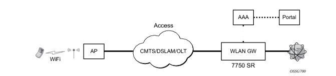
The 7750 SR serves as a WLAN Gateway (WLAN-GW) providing Layer 3 termination and ESM for these subscribers. The connectivity from WLAN AP or AC can be over any existing access technology (DSL, PON, Fiber, DOCSIS, etc.), with Ethernet based connectivity from the access node (DSLAM, OLT, Eth MTU, Layer 2 CMTS) to the WLAN-GW. WLAN-GW functions could be on a standalone 7750 as shown in Figure 142 or could be an add-on functionality on existing 7750 based BNG as shown in
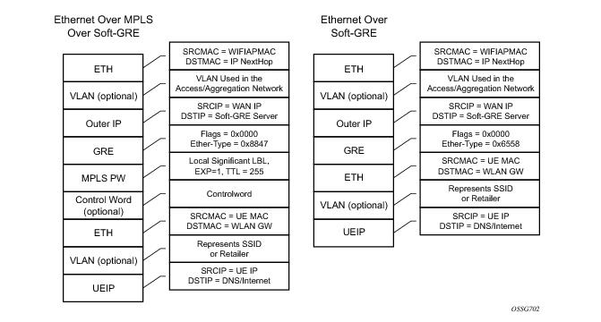
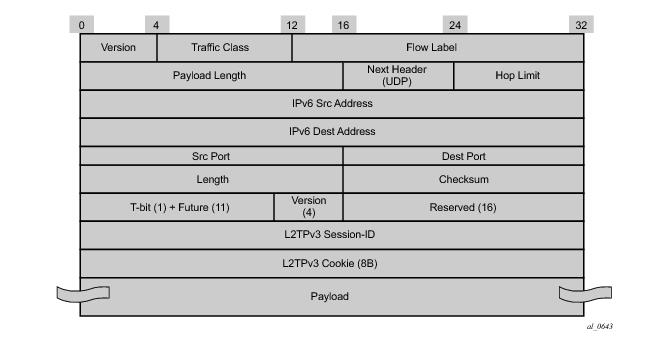
Figure 143. WLAN connectivity to the WLAN-GW could be over a Layer 2 aggregation or an Layer 3 aggregation network (typical when WLAN-GW is upstream of an existing BNG or CMTS). In case of Layer 2 aggregation the connectivity to the WLAN-GW could be tagged or untagged Ethernet. In case of Layer 3 aggregation, supported connectivity option is Ethernet over GRE (or Eth-over-MPLS over GRE) tunnel originating from the AP/AC, and terminating on the WLAN-GW. The WLAN AP acts as a bridge, switching Ethernet frames into a GRE tunnel terminating on an MS-ISA in the WLAN-GW.
The GRE encapsulation is based on RFC 1701/2784, Generic Routing Encapsulation (GRE), WLAN-GW will encapsulate according to RFC 1701 with all the flag fields set to 0, and no optional fields present. WLAN-GW is able to receive both encapsulation specified in RFC 1701 and RFC 2784, with all flag fields set to 0, and no optional fields present in the header.
config isa wlan-gw-group <group-id>
[no] active-iom-limit <number>
[no] description <description-string>
[no] distributed-sub-mgmt
[no] isa-aa-group <aa-group-id>
[no] * iom <slot-number>
nat
[no] radius-accounting-policy <nat-accounting-policy>
[no] session-limits
[no] reserved <num-sessions>
[no] watermarks high <percentage> low <percentage>
[no] shutdown
*B:Dut-C>config>service>vprn>sub-if>grp-if>wlan-gw# info detail
----------------------------------------------
authentication
no authentication-policy
hold-time sec 5
exit
no data-triggered-ue-creation
dhcp
shutdown
active-lease-time min 10
initial-lease-time min 10
no l2-aware-ip-address
no primary-dns
no primary-nbns
no secondary-dns
no secondary-nbns
exit
egress
no agg-rate-limit
no hold-time
qos 1
no scheduler-policy
no shape-multi-client-only
no shaping
exit
gw-address 1.1.1.57
no gw-ipv6-address
no http-redirect-policy
no nat-policy
mobility
hold-time 5
no trigger
exit
router 70
no tcp-mss-adjust
track-mobility
mac-format "aa:"
no radius-proxy-cache
exit
wlan-gw-group 3
vlan-tag-ranges
no default-retail-svc-id
range start 0 end 100
authentication
no authentication-policy
hold-time sec 5
exit
no data-triggered-ue-creation
dhcp
shutdown
active-lease-time min 10
initial-lease-time min 10
no l2-aware-ip-address
no primary-dns
no primary-nbns
no secondary-dns
no secondary-nbns
exit
no http-redirect-policy
no nat-policy
retail-svc-id 35
track-mobility
mac-format "aa:"
no radius-proxy-cache
exit
exit
exit
no shutdown
Downstream traffic can be subjected to aggregate rate-limit per tunnel or per tunnel and per retailer combination (in case of wholesale). Typically a unique SSID is used per retailer for wholesale on the AP, and is reflected via unique dot1Q tag. In the case of a wlan-gw tunnel per AP, the tunnel encapsulation is performed on the tunnel ISA. The downstream traffic on the tunnel IOM is received over B-VPLS from the anchor IOM, and is MAC-in-MAC (802.1ah) encapsulated. I-SID in the packet represents the GRE tunnel or tunnel and retailer combination. SAP-egress QoS policy defining queues (with rates), and FC to queue mapping, can be specified under the wlan-gw interface. This policy is applicable to all tunnels (or tunnel and SSID combinations) associated with the wlan-gw interface, and is attached to corresponding I-SIDs on the B-VPLS SAP. Traffic is shaped into these queues based on configured queue rates. An aggregate rate-limit applied across queues on an I-SID (representing tunnel or tunnel and retailer combination) can be configured under the wlan-gw interface (represented by the wlan-gw node under the group-interface configuration). The aggregate rate-limit works in conjunction with a port-scheduler. The port-scheduler corresponds to the internal port between tunnel ISA and its carrier IOM, and is specified at the wlan-gw IOM group level. The rate-limit includes the B-VPLS encapsulation overhead. The configuration is shown in Figure 145. Queues per I-SID also work with virtual-scheduler (with or without a port scheduler). Virtual-scheduling and aggregate-rate enforcement are mutually exclusive. Configuration is shown in
Figure 146. Egress SAP QoS policy, aggregate rate-limit, port-scheduler, and virtual-schedulers are described in the 7x50 SR OS QoS Guide. The SAP egress QoS policy associated with a wlan-gw interface implicitly creates queues (and scheduler association) on ISIDs as corresponding wlan-gw tunnels are created. General ISID queuing and shaping is defined in the 7x50 SR OS Services Guide.
config>qos#
port-scheduler-policy “lo-gre-port-sched”
max-rate 5000
level 1 rate 1000 cir-rate 1000
level 8 rate 500 cir-rate 500
exit
exit
config>qos>
sap-egress 3 create
queue 1 create
rate 300
port-parent level 1 weight 10 cir-level 1 weight 10
exit
queue 2 create
rate 100
port-parent level 8 weight 10 cir-level 8 weight 10
fc af create
dot1p 2
de-markweight
exit
fc be create
queue 1
dot1p 0
de-mark
exit
fc ef create
queue 2
dot1p 5
de-mark
exit
exit
exit
config>service>ies>sub-if>grp-if>wlan-gw>egress
agg-rate-limit 2000
hold-time 300
qos 3
shaping per-tunnel
shape-multi-client
exit
config>isa>wlan-gw-group#
active-iom-limit 1
tunnel-port-policy " lo-gre-port-sched "
iom 2
iom 3
no shutdown
exit
// hierarchical virtual scheduler
config>qos#
scheduler-policy “virtual-sched-policy”
tier1
scheduler “all-traffic” create
rate 10000
exit
exit
tier2
scheduler “non-voice” create
parent all-traffic cir-level 1
rate 9000
exit
scheduler “voice” create
parent all-traffic level 2 cir-level 2
rate 3000
exit
exit
exit
config>qos>
sap-egress 3 create
queue 1 create
parent “non-voice”
rate 2000 cir 1000
exit
queue 2 create
parent “voice”
rate 500 cir-rate 500
fc be create
queue 1
dot1p 0
de-mark
exit
fc ef create
queue 2
dot1p 5
de-mark
exit
exit
exit
config>service>ies>sub-if>grp-if>wlan-gw>egress
hold-time 300
qos 3
scheduler-policy “virt-sched-policy”
shaping per-tunnel
shape-multi-client
exit
show router 50 wlan-gw soft-gre-tunnels detail
===============================================================================
Soft GRE tunnels
===============================================================================
Remote IP address : 201.1.1.2
Local IP address : 50.1.1.1
ISA group ID : 1
ISA group member ID : 1
Time established : 2012/06/19 20:31:36
Number of UE : 1
Tunnel QoS
----------
Operational state : active
Number of UE : 1
Remaining hold time (s) : N/A
Service Access Points(SAP)
===============================================================================
Service Id : 2147483650
SAP : 2/1/lo-gre:1 Encap : q-tag
Description : Internal SAP
Admin State : Up Oper State : Up
Flags : None
Multi Svc Site : None
Last Status Change : 06/19/2012 07:13:31
Last Mgmt Change : 06/19/2012 20:30:24
-------------------------------------------------------------------------------
Encap Group Specifics
-------------------------------------------------------------------------------
Encap Group Name : _tmnx_SHAPER_GR000 Group Type : ISID
Qos-per-member : TRUE
Members :
1
-------------------------------------------------------------------------------
QOS
-------------------------------------------------------------------------------
E. qos-policy : 3 Q Frame-Based Acct: Disabled
E. Sched Policy : E. Agg-limit : 4000
-------------------------------------------------------------------------------
Encap Group Member 1 Base Statistics
-------------------------------------------------------------------------------
Last Cleared Time : N/A
Forwarding Engine Stats
Packets Octets
For. InProf : 0 0
For. OutProf : 0 0
Dro. InProf : 0 0
Dro. OutProf : 0 0
-------------------------------------------------------------------------------
Encap Group Member 1 Queue Statistics
-------------------------------------------------------------------------------
Packets Octets
Egress Queue 1
For. InProf : 0 0
For. OutProf : 0 0
Dro. InProf : 0 0
Dro. OutProf : 0 0
===============================================================================
-------------------------------------------------------------------------------
No. of tunnels: 1
===============================================================================
show qos scheduler-hierarchy sap 2/1/lo-gre:1 encap-group "_tmnx_SHAPER_GR000" member 1 detail
===============================================================================
Scheduler Hierarchy - Sap 2/1/lo-gre:1
===============================================================================
Egress Scheduler Policy :
-------------------------------------------------------------------------------
Legend :
(*) real-time dynamic value
(w) Wire rates
B Bytes
-------------------------------------------------------------------------------
Root (Egr)
| slot(2)
|--(Q) : -2147483646->2/1/lo-gre:1->EG(_tmnx_SHAPER_GR000):1->1 (Port 2/1/lo-gre Orphan)
| | AdminPIR:10000000 AdminCIR:0
| | AvgFrmOv:100.00
| | AdminPIR:10000000(w) AdminCIR:0(w)
| | CBS:0 B MBS:12582912 B
| | Depth:0 B HiPrio:1376256 B
| | MaxAggRate:4000(w) CurAggRate:0(w)
| |
| | [Within CIR Level 0 Weight 0]
| | Assigned:0(w) Offered:0(w)
| | Consumed:0(w)
| |
| | [Above CIR Level 1 Weight 0]
| | Assigned:4000(w) Offered:0(w)
| | Consumed:0(w)
| |
| | TotalConsumed:0
| | OperPIR:4000 OperCIR:0
| |
| | PktByteOffset:add 0*
| | OnTheWireRates:false
| | ATMOnTheWireRates:false
| | LastMileOnTheWireRates:false
show router 50 wlan-gw soft-gre-tunnels detail
===============================================================================
Soft GRE tunnels
===============================================================================
Remote IP address : 201.1.1.2
Local IP address : 50.1.1.1
ISA group ID : 1
ISA group member ID : 1
Time established : 2012/06/19 20:43:03
Number of UE : 1
Tunnel QoS
----------
Operational state : active
Number of UE : 1
Remaining hold time (s) : N/A
Service Access Points(SAP)
===============================================================================
Service Id : 2147483650
SAP : 2/1/lo-gre:1 Encap : q-tag
Description : Internal SAP
Admin State : Up Oper State : Up
Flags : None
Multi Svc Site : None
Last Status Change : 06/19/2012 07:13:31
Last Mgmt Change : 06/19/2012 20:30:24
-------------------------------------------------------------------------------
Encap Group Specifics
-------------------------------------------------------------------------------
Encap Group Name : _tmnx_SHAPER_GR000 Group Type : ISID
Qos-per-member : TRUE
Members :
1
-------------------------------------------------------------------------------
QOS
-------------------------------------------------------------------------------
E. qos-policy : 3 Q Frame-Based Acct: Disabled
E. Sched Policy : virtual_scheduler_policy E. Agg-limit : -1
-------------------------------------------------------------------------------
Encap Group Member 1 Base Statistics
-------------------------------------------------------------------------------
Last Cleared Time : N/A
Forwarding Engine Stats
Packets Octets
For. InProf : 2 752
For. OutProf : 0 0
Dro. InProf : 0 0
Dro. OutProf : 0 0
-------------------------------------------------------------------------------
Encap Group Member 1 Queue Statistics
-------------------------------------------------------------------------------
Packets Octets
Egress Queue 1
For. InProf : 2 752
For. OutProf : 0 0
Dro. InProf : 0 0
Dro. OutProf : 0 0
===============================================================================
-------------------------------------------------------------------------------
No. of tunnels: 1
===============================================================================
show qos scheduler-hierarchy sap 2/1/lo-gre:1 encap-group "_tmnx_SHAPER_GR000" member 1 detail
===============================================================================
Scheduler Hierarchy - Sap 2/1/lo-gre:1
===============================================================================
Egress Scheduler Policy :
-------------------------------------------------------------------------------
Legend :
(*) real-time dynamic value
(w) Wire rates
B Bytes
-------------------------------------------------------------------------------
Root (Egr)
| slot(2)
|--(S) : virtual_scheduler (Port 2/1/lo-gre)
| | AdminPIR:4000 AdminCIR:0(sum)
| |
| | AvgFrmOv:105.31(*)
| | AdminPIR:4212(w) AdminCIR:0(w)
| |
| | [Within CIR Level 0 Weight 0]
| | Assigned:0(w) Offered:0(w)
| | Consumed:0(w)
| |
| | [Above CIR Level 1 Weight 1]
| | Assigned:4212(w) Offered:0(w)
| | Consumed:0(w)
| |
| |
| | TotalConsumed:0(w)
| | OperPIR:3999
| |
| | [As Parent]
| | Rate:3999
| | ConsumedByChildren:0
| |
| |
| |--(Q) : -2147483646->2/1/lo-gre:1->EG(_tmnx_SHAPER_GR000):1->1
| | | AdminPIR:10000000 AdminCIR:0
| | | AvgFrmOv:105.31(*)
| | | CBS:0 B MBS:12582912 B
| | | Depth:0 B HiPrio:1376256 B
| | |
| | | [Within CIR Level 0 Weight 1]
| | | Assigned:0 Offered:0
| | | Consumed:0
| | |
| | | [Above CIR Level 1 Weight 1]
| | | Assigned:3999 Offered:0
| | | Consumed:0
| | |
| | | TotalConsumed:0
| | | OperPIR:4000 OperCIR:0
| | |
| | | PktByteOffset:add 0*
| | | OnTheWireRates:false
| | | ATMOnTheWireRates:false
| | | LastMileOnTheWireRates:false
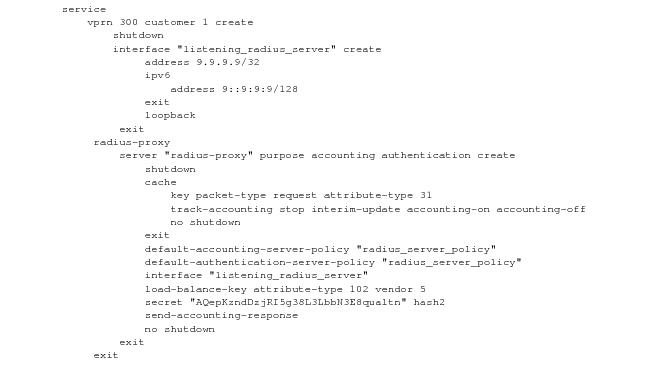
RADIUS proxy can be configured per service router (base or VPRN). The proxy acts as a server towards the WIFI AP RADIUS clients, and as a client towards RADIUS server(s). Therefore, both client and server parts of the RADIUS proxy need to be configured. The attribute from access-request or response message that serves as the key for the cache is configurable. The key configuration is mandatory for enabling the cache. Commonly the key is the MAC address of the UE, which is available in subsequent DHCP request, and used to locate the cache entry. The UE’s MAC address is typically available in the Calling-station-Id attribute (31) in the RADIUS access-request message from the AP. The proxy can be configured for both authentication and accounting. The radius server policies referred by RADIUS proxy are configured under “aaa” context. If caching is enabled in the RADIUS proxy, the subscriber attributes returned in access-accept are cached. These can include 802.1x credentials/keys, IP address or pool, DNS information, default gateway information, retail-service-id, SLA-profile, filter parameters, charging information, session keys (MS-MPPE-RECV-KEY, MS-MPPE-SEND-KEY) etc. If subsequent DHCP DISCOVER is not received within the configured timeout, the cache entry is removed.
config>service>ies>
config>service>vprn>
description "Default Description For VPRN ID 50"
interface "listening_radius_server" create
address 9.9.9.9/32
loopback
exit
radius-proxy
server "radius_proxy" purpose accounting authentication create
cache
key packet-type request attribute-type 31
timeout min 5
track-accounting stop interim-update accounting-on accounting-off
no shutdown
exit
default-accounting-server-policy "radius_acct_server_policy"
default-authentication-server-policy "radius_Auth_server_policy"
interface "listening_radius_server"
load-balance-key attribute-type 102 vendor 5
secret "AQepKzndDzjRI5g38L3LbbN3E8qualtn" hash2
send-accounting-response
no shutdown
exit
config>service>vprn
radius-server
server "radius_server" address 100.100.100.2 secret "9OkclHYDDbo9eHrzFmuxiaO/LAft3Pw"
hash2 port 1812 create
exit
exit
config>aaa
radius-server-policy "radius_server_policy" create
servers
router 50
access-algorithm hash-based
source-address 10.1.1.1
timeout min 1
hold-down-time 2
server 1 name "radius_server"
exit
config>subscriber-mgmt
local-user-db "radius_ludb" create
dhcp
match-list service-id
host "default" create
auth-policy "auth_policy_1"
match-radius-proxy-cache
fail-action continue
match mac
server router 50 name "radius_proxy"
exit
no shutdown
exit
no shutdown
exit
exit
config>subscriber-mgmt
sla-profile "portal-redirect" create
ingress
ip-filter 10
exit
exit
exit
system>config>filter
ip-filter 10 create
entry 1 create
match protocol udp
dst-port range 67 68
exit
action forward
exit
entry 2 create
match protocol tcp
dst-port eq 80
exit
action http-redirect "http://www.google.ca"
exit
exit
exit
config>service>vprn
dhcp
local-dhcp-server "dhcp" create #### create local DHCP server
pool “1” create #### define Pool
options
dns-server 8.8.8.8 8.8.4.4
lease-time min 5
exit
subnet 128.203.254.180/30 create
options
subnet-mask 255.255.0.0
default-router 128.203.254.181
exit
address-range 128.203.254.182 128.203.254.183
exit
exit
exit
exit
interface "DHCP-lb" create #### loopback interface with DHCP server
address 10.1.1.1/32
local-dhcp-server "dhcp"
loopback
exit
subscriber-interface "sub-int" create #### subscriber interface
address 128.203.254.181/30 #### Subnets out of which UE
address 10.10.0.1/16 ###### addresses are allocated.
group-interface "group-int" wlgw create
sap-parameters
sub-sla-mgmt
def-sla-profile "sla_def"
def-sub-profile "sub_def"
sub-ident-policy "sub_ident"
exit
exit
exit
dhcp
proxy-server
emulated-server 10.10.0.1 #### proxy to get IP address from AAA
lease-time min 5 #### or from DHCP server. Can provide
no shutdown #### split lease (shorter lease towards client,
exit #### and longer lease towards AAA or DHCP server.
no option
server 10.1.1.1 #### DHCP local server
trusted
lease-populate 32000
gi-address 128.203.254.181
user-db "radius_ludb" #### LUDB for proxy cache co-relation
no shutdown
exit
exit
config>service>ies>
config>service>vprn>
subscriber-interface <if-name>
group-interface <if-name> wlangw
wlan-gw
[no] router (base | <vprn-id>) # tunnel service context
[no] wlan-gw-group <group-id>
....snip
mobility
[no] trigger {data | iapp}
[no] hold-time <seconds> // [0..255 secs]
exit
exit
exit
config>service>ies>
config>service>vprn>
subscriber-interface <if-name>
group-interface <if-name> wlangw
wlan-gw
[no] router (base | <vprn-id>) # tunnel service context
[no] wlan-gw-group <group-id>
....snip
vlan-tag-ranges # Precedence for retail-service-id:
# RADIUS, vlan-retail-service-map, default-retail-svc
[no] vlan start <start-tag> end <end-tag> retail-svc-id <svc-id>
[no] default-retail-svc-id
exit
exit
exit
*A:Dut-C# show router 4 interface "grp-vprn_ue-2/1/2:50" detail
=====================================================================
Interface Table (Service: 4)
=====================================================================
--------------------------------------------------------------------
Interface
--------------------------------------------------------------------
If Name : grp-vprn_ue-2/1/2:50
Sub If Name : ies-4-20.0.0.1
Red If Name :
Admin State : Up Oper (v4/v6) : Up/Up
Protocols : None
WLAN Gateway details
Administrative state : in-service
Router : 50
IP address : 50.1.1.3
IPv6 address : 2032::1:1:3
ISA group ID : 1
Egr shaping : none
Egr shape multi UE only : false
Egr qos policy ID : (Not Specified)
Egr scheduler policy : (Not Specified)
Egr agg rate limit (kbps) : (Not Specified)
Egr qos resrc hold time (s) : 0
Mobility trigger : data iapp
Mobility ARP AP : enabled
Mobility hold time (s) : 0
Default retailer service : (Not Specified)
TCP MSS adjust : (Not Specified)
Number of tunnels : 0
Last management change : 02/19/2014 17:48:52
config>subscriber-mgmt>wlan-gw
serving-network mcc “123” mnc “45”
mgw-profile “pgw-west-mno1” [create]
description “mgw profile for MNO north-east PGW”
interface-type s2b
ip-ttl 255
keep-alive interval 60 retry-count 3 timeout 10
message-retransmit timeout 30 retry-count 3
exit
config>router
config>service>vprn
apn “internet.mno1.apn”
mgw-map
address 33.1.1.1/32 “pgw-west-mno1”
address 34.1.1.1/32 “ggsn-east-mno1”
exit
config>service>vprn>dns
primary-dns 130.1.1.1
secondary-dns 131.1.1.1
tertiary-dns 132.1.1.1
ipv4-source-address 170.1.1.1
exit
Table 24describes 3GPP attributes and ALU specific attributes related to GTP signaling are supported.
system>config>filter
ip-filter 10 create
entry 1 create
match protocol udp
dst-port eq 4000
exit
action gtp-local-breakout
exit
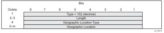
The WLAN location information consists of the TWAN Identifier IE as described in 29 274 V11.6.0 (2013-04) and is sent in GTPv2 “create session request” message. If present, this IE carries BSSID (MAC address of the AP) and the SSID. WLAN-GW learns the AP’s MAC@ from calling-station-id attribute in the RADIUS messages from the AP (both authentication and accounting messages) or from circuit-id in DHCP DISCOVE or REQUEST messages. In this release, the IE is only sent at session creation time. Therefore, it reports location on initial attach, on handover from LTE to WIFI, and on AP mobility across WLAN-GWs. Mobility across APs anchored on the same WLAN-GW does not result in location update. 3GPP release 11 does not define location update mechanism for S2a.
config>subscriber-mgmt>wlan-gw>
mgw-profile "pgw-west-mn01"
[no] report-wlan-location
The AP’s MAC@ and IP@ are provided to AAA server in RADIUS messages during EAP authentication and accounting. If AAA provides the cellular location (corresponding to this AP) in 3GPP attribute 3GPP-User-Location-Info in access-accept, and location reporting is enabled via CLI. The ULI IE will be included in GTPv2 “create session request”. The
3GPP-User-Location-Info attribute is described in 3GPP TS 29.061 v9.3.0.
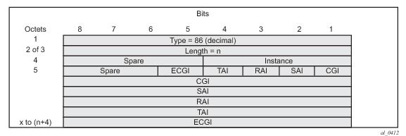
The “User Location Info” IE (as shown in Figure 154) can be included in create-pdp-context message as described in 3GPP TS 29.060 V10.1.0. The geographic location type field describes the type of location included in the “Geographic Location” field that follows. The location can be CGI (cell global identification), SAI (service area identity), or RAI (routing area identity). The formats for these location identifiers are defined in the same reference
3GPP TS 29.060 V10.1.0.
*A:Dut-C>config>subscr-mgmt>wlan-gw>mgw-profile$ /show subscriber-mgmt wlan-gw
mgw-profile "test"
====================================================================
WLAN Mobile Gateway profile "test"
====================================================================
Description : (Not Specified)
Retransmit timeout (s) : 5
Retransmit retries : 3
Keepalive interval (s) : 60
Keepalive retries : 4
Keepalive retry timeout (s) : 5
Time to live : 255
Interface type : s2a
Charging char home UE : (None)
Charging char roaming UE : (None)
Session hold time (s) : 30
Report WLAN location : enabled
Last management change : 02/21/2014 16:31:12
GGSN uplink GBR (Kbps) : 5000
GGSN uplink MBR (Kbps) : 5000
GGSN downlink GBR (Kbps) : 2000
GGSN downlink MBR (Kbps) : 2000
GGSN Alloc/Retention Prio : 1
GGSN last management change : 02/19/2014 17:31:55
PGW uplink GBR (Kbps) : 0
PGW uplink MBR (Kbps) : 0
PGW downlink GBR (Kbps) : 0
PGW downlink MBR (Kbps) : 0
PGW Alloc/Retention Prio : 1
PGW Qos Class ID : 8
PGW last management change : 02/19/2014 17:31:55
=====================================================================
show router wlan-gw
mobile-gateway – Display mobile gateway information
mgw-map – Display the mobile gateway map
mgw-address-cache – Display the mobile gateway’s DNS lookup address cache.
show router wlan-gw mgw-address-cache [apn <apn-string>]
<apn-string> : [80 chars max]
show router wlan-gw mobile-gateway
[mgw-profile <profile-name>] [local-address <ip-address>] [control <protocol>]
remote-address <ip-address> [udp-port <port>]
remote-address <ip-address> [udp-port <port>] statistics
<profile-name> : [32 chars max]
<ip-address> : ipv4-address - a.b.c.d
<ipv6-address - x:x:x:x:x:x:x:x (eight 16-bit pieces)
x:x:x:x:x:x:d.d.d.d
x - [0..FFFF]H
d - [0..255]D
<protocol> : gtpv1-c|gtpv2-c
<port> : [1..65535]
===============================================================================
Mobile gateways
===============================================================================
Remote address : 5.20.1.2
UDP port : 2123
-------------------------------------------------------------------------------
State : up
Local address : 5.20.1.3
Profile : default
Control protocol : gtpv1-c
Restart count : 3
Time : 2012/06/28 08:07:11
===============================================================================
Mobile Gateway address cache
===============================================================================
APN : full.dotted.apn.apn.epc.mnc010.mcc206.3gppnetwork.org
-------------------------------------------------------------------------------
Mobile Gateway address : 5.20.1.2
Time left (s) : 3587
-------------------------------------------------------------------------------
No. of cache entries: 1
No. of Mobile gateways: 1
===============================================================================
show subscriber-mgmt wlan-gw
gtp-session - Display GTP session information
gtp-statistics - Display GTP statistics
mgw-profile - Display Mobile Gateway profile information
show subscriber-mgmt wlan-gw gtp-session
imsi <imsi> apn <apn-string>
[mgw-address <ip-address>] [mgw-router <router-instance>] [remote-control-teid <teid>] [local-
control-teid <teid>] [detail]
imsi <imsi>
<imsi> : [a string of digits between 9 and 15 long]
<apn-string> : [80 chars max]
<ip-address> : ipv4-address - a.b.c.d
<ipv6-address> : x:x:x:x:x:x:x:x (eight 16-bit pieces)
x:x:x:x:x:x:d.d.d.d
x - [0..FFFF]H
d - [0..255]D
<router-instance> : <router-name>|<service-id>
router-name - "Base"
service-id - [1..2147483647]
<teid> : [1..4294967295]
show subscriber-mgmt wlan-gw gtp-statistics
show subscriber-mgmt wlan-gw mgw-profile
<profile-name>
<profile-name> associations
mgw-profile
<profile-name> : [32 chars max]
===============================================================================
GTP sessions
===============================================================================
IMSI : 206100000000041
APN : full.dotted.apn.mnc010.mcc206.gprs
-------------------------------------------------------------------------------
Mobile Gateway router : "Base"
Mobile Gateway address : 5.20.1.2
Remote control TEID : 1119232
Local control TEID : 4293918976
Bearer 5 rem TEID : 1074861061
Bearer 5 loc TEID : 4293919013
-------------------------------------------------------------------------------
No. of GTP sessions: 1
===============================================================================
===============================================================================
WLAN Mobile Gateway profile "default"
===============================================================================
Description : (Not Specified)
Retransmit timeout (s) : 5
Retransmit retries : 3
Keepalive interval (s) : 60
Keepalive retries : 4
Keepalive retry timeout (s) : 5
Time to live : 255
Interface type : s2a
Last management change : 06/28/2012 06:05:30
===============================================================================
=============================================================================
GTP statistics
=============================================================================
tx echo requests : 1
tx echo responses : 0
tx errors : 0
rx echo requests : 0
rx echo responses : 1
rx errors : 0
rx version not supported : 0
rx zero TEID responses : 0
path faults : 0
path restarts : 0
tx invalid msgs : 0
tx create PDP context requests : 0
tx create PDP context responses : 0
tx delete PDP context requests : 0
tx delete PDP context responses : 0
tx create session requests : 1
tx create session responses : 0
tx delete session requests : 0
tx delete session responses : 0
tx delete bearer requests : 0
tx delete bearer responses : 0
tx error indication count : 0
rx invalid msgs : 0
rx create PDP context requests : 0
rx create PDP context responses : 0
rx delete PDP context requests : 0
rx delete PDP context responses : 0
rx create session requests : 0
rx create session responses : 1
rx delete session requests : 0
rx delete session responses : 0
rx delete bearer requests : 0
rx delete bearer responses : 0
rx error indication count : 0
rx invalid pkt length : 0
rx unknown pkts : 0
rx missing IE pkts : 0
rx bad IP header pkts : 0
rx bad UDP header pkts : 0
============================================================================
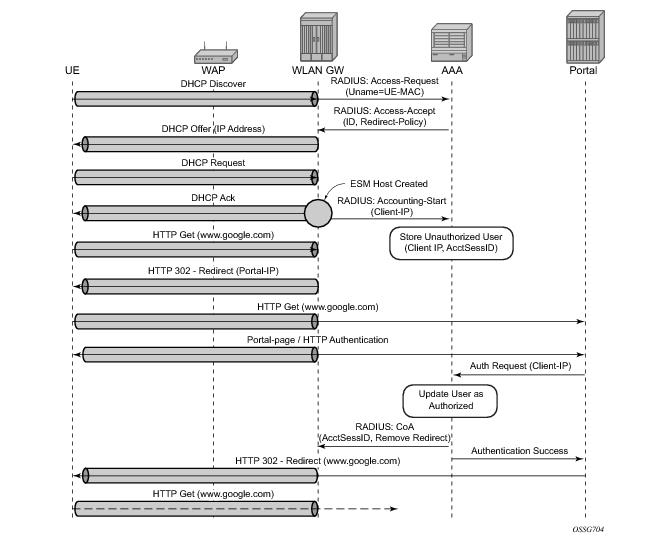
“Migrant users” are UEs that connect to an SSID, but move out of the range of the access-point before initiating or completing authentication. For open-SSIDs, a migrant user may stay in the range of the access-point just enough to get a DHCP lease from the WLAN-GW. In real WIFI deployments with portal authentication, it has been observed that a large percentage of users are migrant, such as get a DHCP lease but do not initiate or complete authentication. Prior to this feature, an ESM host is created when DHCP completes. This results in consumption of resources on both CPM and IOM, limiting the ESM scale and performance for fully authenticated active users. This feature adds support to only create an ESM host after a user has been fully authenticated, either via web portal or with a AAA server based on completing EAP exchange. In addition, with this feature L2-aware NAPT is enabled on the ISA, such that each UE gets the same shared configured inside IP@ from the ISA via DHCP. Until a user is authenticated, forwarding of user traffic is constrained (via policy) to only access DNS and portal servers. Each user is allocated a small number of configured NAT outside ports to minimize public IP address consumption for unauthenticated users. Once the user is successfully authenticated, as indicated via a RADIUS COA on successful portal authentication, an ESM host is created, and the L2-aware NAT is applied via a normal per-subscriber NAT policy. The inside IP address of the user does not change. The outside IP pool used is as per the NAT policy, and the L2-aware NAT could be 1:1 or NAPT with larger number of outside ports than in the un-authenticated phase. If a user is already pre-authenticated (for example, if RADIUS server remembers the MAC@ of the UE from previous successful portal authentication), then the initial access-accept from RADIUS will trigger the creation of the ESM host.
However, if a user needs portal authentication (as indicated in access-accept), then while the user is pending authentication, forwarding is restricted to DNS and portal servers via the redirect policy. The redirect policy is an IP ACL that restricts forwarding based on IP destination, destination port, and protocol, and also specifies http-redirect for http traffic that does not match any of the forwarding rules. The URL for re-direct is configured in the redirect policy or can be provided in authentication-accept. A maximum of 16 redirect policies can be created in the system, with a maximum of 64 forward rules across all redirect policies. During this “authentication pending” phase all forwarded traffic is subjected to L2-aware NAT on the ISA. The NAT policy to use for these users can be configured on the wlan-gw interface or per VLAN range under the wlan-gw interface. After an access-accept has been received from RADIUS for such a user, the next http packet triggers a redirect function from the ISA, and an http 302 is sent to the client. The redirect can be configured to append original-URL, subscriber’s MAC address and IP address to the redirect URL sent back in http 302. The client presents its credentials to the portal and once it is successfully authenticated, a COA is generated from the RADIUS server (triggered by the portal). The COA message triggers creation of an ESM host with the subscriber configuration contained in the COA such as subscriber-profile, SLA-profile, NAT-profile and application-profile. From this point normal ESM based forwarding occurs for the subscriber.
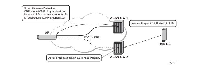
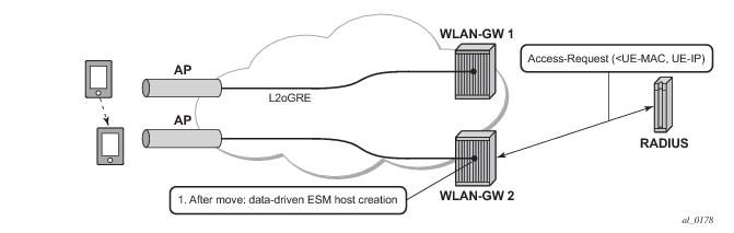
With data-triggered-ue-creation configured under wlan-gw group interface or per VLAN range (such as, per one or more SSIDs), the first UDP or TCP packet received on WLAN-GW ISA from an unknown subscriber (with no prior state, such as an unknown MAC address) will trigger RADIUS authentication from the ISA. The authentication is based on configured isa-radius-policy (under aaa context). If RADIUS authentication succeeds, then ESM host is created from the CPM. The ESM host can get deleted based on idle-timeout. Data-triggered authentication and subscriber creation enables stateless inter WLAN-GW redundancy, as shown in
Figure 155. If the AP is configured with a backup WLAN-GW address (or FQDN), it can tunnel subscriber traffic to the backup WLAN-GW, when it detects failure of the primary WLAN-GW (based on periodic liveness detection). With “data-triggered-ue-creation” configured, the first data packet results in authentication and ESM host creation on the backup WLAN-GW. If the subscriber had obtained an IP address via DHCP with L2-aware NAT on the primary WLAN-GW, it can retain it with L2 aware NAT on the backup WLAN-GW. The NAT outside pool for the subscriber changes on the backup WLAN-GW based on local configuration. For a subscriber that needs to be anchored on GGSN/PGW (as indicated via RADIUS access-accept), RADIUS server will return the IP address of PGW/GGSN where the UE was anchored before the switch-over. GTP tunnel is then signaled with “handover indication” set. The PGW/GGSN must return the requested IP address of the UE, which is the address with which the UE originated data packet that triggered authentication.
#------------------------------------------------------
NAT configuration for migrant and authenticated users
#------------------------------------------------------
service
vprn 300 customer 1 create
nat
inside
l2-aware
address 21.1.1.1/16
exit
exit
outside
pool "migrant_outside_pool" nat-group 1 type wlan-gw-anchor create
address-range 22.22.0.0 22.22.0.255 create
exit
no shutdown
exit
pool "wifi_outside_pool" nat-group 1 type l2-aware create
address-range 22.0.0.0 22.0.0.255 create
exit
no shutdown
exit
exit
exit
exit
nat
nat-policy "migrant_nat_300" create
pool "migrant_outside_pool" router 300
timeouts
tcp-established min 1
exit
exit
nat-policy "wifi_nat_300" create
pool "wifi_outside_pool" router 300
exit
exit
#--------------------------------------------------------------------------------
echo "AAA Configuration" - ISA-RADIUS-Policy for authentication from WLAN-GW ISA
#--------------------------------------------------------------------------------
aaa
isa-radius-policy "wifi_isa_radius" create
description "Default authentication policy for migrant users"
password "i2KzVe9XPxgy4KN2UEIf6jKeMT3X4mT6JcUmnnPZIrw" hash2
servers
router "Base"
source-address-range 100.100.100.4
server 1 create
authentication
coa
ip-address 100.100.100.2
secret "ABIQRobhHXzq13ycwqS74FSrj.OdTwh5IdjhRB.yAF." hash2
no shutdown
exit
exit
exit
radius-server-policy "radius_server_policy" create
servers
router "Base"
server 1 name "radius_server"
exit
exit
exit
#--------------------------------------------------
echo "Subscriber-mgmt Configuration" - Redirect Policy
#--------------------------------------------------
subscriber-mgmt
http-redirect-policy "migrant_redirect" create
url "portal.ipdtest.alcatel-lucent.com:8081/start/?mac=$MAC&url=$URL&ip=$IP"
portal-hold-time 10
forward-entries
dst-ip 8.8.8.1 protocol tcp dst-port 8081
dst-ip 8.8.8.7 protocol tcp dst-port 8007
dst-ip 8.8.8.8 protocol udp dst-port 53
exit
exit
exit
service
#----------------------------------------------------------------
echo "migrant user configuration under wlan-gw group interface”
#---------------------------------------------------------------
vprn 300 customer 1 create
subscriber-interface "ies-4-20.1.1.1" create
address 20.1.1.1/16
group-interface "grp-vprn_ue-2/1/2:51" wlangw create
sap-parameters
sub-sla-mgmt
def-sla-profile "slaprof_1"
def-sub-profile "subprof_1"
sub-ident-policy "identprof"
exit
exit
dhcp
proxy-server
emulated-server 20.1.1.1
no shutdown
exit
trusted
lease-populate 32767
user-db "radius_ludb"
no shutdown
exit
host-connectivity-verify interval 1000
wlan-gw
gw-address 50.1.1.4
mobility
hold-time 0
trigger data iapp
exit
router 50
wlan-gw-group 1
vlan-tag-ranges
range start 100 end 100
authentication
authentication-policy "wifi_isa_radius"
exit
data-triggered-ue-creation
dhcp
l2-aware-ip-address 21.1.1.2
primary-dns 130.1.1.1
secondary-dns 131.1.1.1
no shutdown
exit
nat-policy "migrant_nat_4"
exit
exit
no shutdown
exit
exit
exit
exit
With DSM, in addition to initial DHCP and authentication, once the subscriber state exists on the anchor ISA, accounting and DHCP renews are also handled from the anchor ISA for the UE. This allows a higher UE scale and better control plane performance (including DHCP transactions per second, rate of authentications, and web redirects) due to load-balancing amongst set of ISAs in the WLAN-GW group. With DSM, the UE data-plane functions (such as per UE IP filtering, ingress/egress policing, legal intercept, per UE counters, and web-redirect) are performed on the ISA.
The decision to create an authenticated UE as an ESM or DSM UE can be controlled from RADIUS via inclusion of Alc-Wlan-Ue-Creation-Type VSA. The VSA can be included in access-accept for a UE that is auto-signed-in (for example, it does not need web redirect to portal), or in a COA message triggered to remove web redirect for a UE after successful portal authentication. The VSA is described in the RADIUS guide. If
Alc-Wlan-Ue-Creation-Type is not present in access-accept (for auto-signed UE) or in the COA message (for UE creation of portal authenticated UE), then the UE is created as an ESM host. In this release DSM is not supported for dual-stack UEs or UEs which require a GTP host. If
Alc-Wlan-Ue-Creation-Type indicates a DSM UE then any IPv6 or GTP related parameters in access-accept or COA will be ignored, and the UE will be created as a DSM host.
Alc-Wlan-Ue-Creation-Type cannot be changed mid-session via COA. A COA containing
Alc-Wlan-Ue-Creation-Type for an existing UE does not result in any change of state, and is NACK’ed.
Based on DHCP and L2 NAT configuration on the ISA, the configured IP address (l2-aware-ip-address configured under vlan-range or default vlan-range) is assigned to the user via DHCP. A different DHCP lease-time can be configured for an un-authenticated and an authenticated user for which an ESM or DSM host has been created. DHCP return options, for example, DNS and NBNS server addresses can be configured. This configuration can be per soft-wlan-gw group interface (by explicitly configuring it under vlan-range default), or per VLAN range (where a VLAN tag corresponds to an SSID). By default, for open SSIDs, DHCP DORA is completed, and authentication request is is sent to AAA server only on reception of the first Layer 3 packet. However, with a authenticate-on-dhcp command configured under vlan-range (default or specific range), authentication can be triggered on received DHCP DISCOVER or REQUEST when no UE state is present. If UE anchoring on GGSN/PGW is required, then
authenticate-on-dhcp must be enabled, since the decision to setup GTP tunnel (in which case the IP@ for the UE comes from the GGSN/PGW) is based on RADIUS response.
The authentication is initiated from RADIUS client on the ISA anchoring the user, based on an isa-radius-policy (configured under aaa) and specified on the wlan-gw group-interface. This support exists in prior releases and is described in
Authentication and Forwarding . The auth-policy can contain up to ten servers, five of which can be for authentication and all ten can be COA servers.
In order to generate accounting updates for DSM UEs, an accounting policy (type isa-radius-policy) must be configured under the aaa node and specified under
vlan-range (
default or
specific range) on the wlan-gw interface. Accounting for DSM UEs includes
accounting-start,
accounting-stop and
interim-updates. Interim-update interval is configurable under vlan-range on wlan-gw interface. The user-name format to be included in RADIUS messages is configurable in the auth-policy and accounting-policy via the
user-name-format command. By default, the user-name contains the UE MAC address, but can be configured to include the UEs MAC address and IP address, or circuit-id or DHCP vendor options. If
authenticate-on-dhcp is enabled, then the IP address for the UE is not known prior to authentication, and, if the user-name is configured to contain both MAC and IP address, then only the MAC address will be included.
*A:Dut-1>config>aaa# info
----------------------------------------------
isa-radius-policy "isaRadiusPol1" create
user-name-format mac mac-format alu
acct-include-attributes
acct-delay-time
acct-trigger-reason
called-station-id
calling-station-id
circuit-id
dhcp-options
dhcp-vendor-class-id
frame-counters
framed-ip-addr
framed-ip-netmask
hardware-timestamp
inside-service-id
mac-address
multi-session-id
nas-identifier
nas-port-id
nas-port-type
octet-counters
outside-ip
outside-service-id
port-range-block
release-reason
remote-id
session-time
subscriber-id
ue-creation-type
user-name
wifi-rssi
wifi-ssid-vlan
exit
The isa-radius-policy for auth/COA and accounting specifies the server selection method for the servers specified in the policy with respect to load-balancing and failure of one or more servers. The three methods implemented include:
*A:Dut-1>config>aaa# info
isa-radius-policy "isaRadiusPol1" create
nas-ip-address-origin system-ip
password "6mNsKxvTe.0.nNCTIpGFcu.rr/qtdijazQ3ED8WAFfk" hash2
user-name-format mac mac-format alu release-reason
servers
access-algorithm hash-based
retry 3
router "Base"
source-address-range 81.1.0.1
timeout sec 5
server 1 create
accounting port 1813
authentication port 1812
coa port 3799
ip-address 10.13.0.2
secret "3BmWbBfDO38hPY8DtLFn8bYDBaduy6w.ogeSUsouoHc" hash2
no shutdown
exit
exit
exit
----------------------------------------------
*A:Dut-1>config>aaa#
Filtering based on protocol, destination IP, destination port or any combination is supported for traffic to and from the UE. The match entries and corresponding actions can be specified within the dsm-ip-filter which can be created in the
subscriber-mgmt>wlan-gw>dsm context. The filter can be associated with a vlan-range (default or specific vlan-range) on wlan-gw interface, in which case all subscribers associated with the vlan-range will be associated with an instance of this filter.
A:system>config>subscr-mgmt>wlan-gw>dsm>dsm-ip-filter# info
----------------------------------------------
dsm-ip-filter “foo” create
default-action forward
entry 1 create
action drop
match protocol udp
dst-ip 203.0.113.0/32
dst-port eq 53
exit
exit
ipv6
default-action forward
entry 1 create
action drop
match protocol tcp
dst-ip 2001:db8::/120
dst-port eq 80
exit
exit
exit
----------------------------------------------
*A:vsim>config>service>vprn# info
----------------------------------------------
subscriber-interface "s1" create
group-interface "g1" wlangw create
wlan-gw
vlan-tag-ranges
range default
distributed-sub-mgmt
dsm-ip-filter “foo”
exit
exit
exit
exit
----------------------------------------------
Per UE policing for both ingress and egress direction is supported. Policers can be created under subscriber-mgmt>wlan-gw>dsm. The policers can be of type single-bucket (PIR) bandwidth limiting or dual-bucket (PIR and CIR) bandwidth limiting. In this release only policer action supported is permit-deny i.e. non-conformant traffic is dropped, as opposed to marked out-of-profile. The administrative peak and committed rates and peak and committed burst sizes are configurable. For single-bucket bandwidth policers, cir and cbs are not applicable, and only pir and mbs are configurable.
*A:vsim>config>subscr-mgmt>wlan-gw>distributed-sub-mgmt>dsm-policer# info detail
----------------------------------------------
no description
action permit-deny
cbs 100
mbs 200
rate 1000 cir 500
The policers can be associated with a vlan-range (default or specific vlan-range) on wlan-gw interface, in which case all subscribers associated with the vlan-range will be associated with an instance of these policers. These ingress and egress policers can be overridden on per UE basis via RADIUS access-accept or COA. The new VSAs Alc-Wlan-Dsm-Ingress-Policer and
Alc-Wlan-Dsm-Egress-Policer are defined for specifying the per UE policers from RADIUS. The VSAs are defined in the
7750 SR-OS RADIUS Attributes Reference Guide. If the policers specified in access-accept are not found the message is dropped. If the policers specified in COA are not found, a NACK is sent back.
*A:vsim>config>service>vprn# info
----------------------------------------------
subscriber-interface "s1" create
group-interface "g1" wlangw create
wlan-gw
vlan-tag-ranges
range default
distributed-sub-mgmt
egress-policer "silver-egress"
ingress-policer "silver-ingress"
exit
exit
exit
exit
----------------------------------------------
A:Dut-1>config>mirror# info
----------------------------------------------
mirror-dest 60000 type ip-only create
encap
layer-3-encap ip-udp-shim create
gateway create
ip src 1.1.1.1 dest 2.2.2.2
udp src 2048 dest 2049
exit
exit
exit
no shutdown
exit
----------------------------------------------
A:Dut-1>config>li# info
----------------------------------------------
li-source 60000
wlan-gw
dsm-subscriber mac 00:00:00:07:02:03
intercept-id 10000
session-id 20000
exit
exit
no shutdown
exit
LI can be enabled or disabled from RADIUS via inclusion of the Alc-LI-Action VSA in access-accept or COA. The
Alc-LI-Destination VSA is required to indicate the mirror-dest service that the DSM UE under LI is associated with. The Intercept-Id and Session-Id for a DSM UE can be provided from RADIUS access-accept or COA via inclusion of Alc-LI-Intercept-Id and Alc-LI-Session-Id VSAs. These LI related VSAs are described in the RADIUS guide.
Similar to data-triggered UE creation with ESM, a DSM UE can also be created based on data-triggered authentication discussed in Data Triggered Subscriber Creation . The decision to create ESM versus DSM UE is based on the value of RADIUS VSA Alc-Wlan-Ue-Creation-Type present in the access-accept message. The data-triggered authentication and UE creation if configured provides for WLAN-GW IOM redundancy. The DSM UE is created on the standby ISA based on successful data-triggered authentication. Also, inter-chassis redundancy is supported for DSM UE based on data-triggered authentication, and is identical to ESM (as described in
Data Triggered Subscriber Creation .
A:Dut-1# tools dump li wlan-gw ue
No sessions on Slot #2 MDA #1 match the query
======================================================================
Matched 2 sessions on Slot #2 MDA #2
=====================================================================
UE-Mac : 00:00:00:07:02:03 Mirror Service : 60000
LI Intercept-Id : 10000 LI Session-Id : 20000
---------------------------------------------------------------------
UE-Mac : 00:00:00:07:02:08 Mirror Service : 60000
LI Intercept-Id : 42 LI Session-Id : 2013
--------------------------------------------------------------------
=====================================================================
A:Dut-1>show>li# li-source 60000
===============================================================================
Mirror Service
===============================================================================
Service Id : 60000 Type : ipOnly
-------------------------------------------------------------------------------
L3 encap type : ip-udp-shim Router : Router: Base
Direction bit : No
Primary gateway
Source IP : 1.1.1.1 Dest IP : 2.2.2.2
Source UDP port : 2048 Dest UDP port : 2049
===============================================================================
Local Sources
-------------------------------------------------------------------------------
Admin State : Up
-------------------------------------------------------------------------------
WLAN Gateway LI sources
-------------------------------------------------------------------------------
MAC-Address Intercept-Id Session-Id
-------------------------------------------------------------------------------
00:00:00:07:02:03 10000 20000
===============================================================================
A:system>config>subscr-mgmt>wlan-gw# info
----------------------------------------------
virtual-chassis-identifier "wlan_gw_pair"
----------------------------------------------
A:system>config>service>vprn>sub-if>wlan-gw# info
----------------------------------------------
pool-manager
watermarks high 85 low 66
wlan-gw-group 1
dhcpv6-client
server 2001:db8::1
lease-query max-retry 2
slaac
pool-name "pool_ue_pd_v6_slaac"
no shutdown
exit
ia-na
pool-name "pool_ue_pd_v6_dhcp6"
no shutdown
exit
exit
exit
----------------------------------------------
A:system>config>service>vprn>sub-if>grp-if>wlan-gw>ranges>range# info
----------------------------------------------
...
authenticate-on-dhcp
...
dhcp6
active-preferred-lifetime hrs 1
active-valid-lifetime hrs 1
no shutdown
exit
slaac
active-preferred-lifetime hrs 1
active-valid-lifetime hrs 1
no shutdown
exit
...
----------------------------------------------
Configuration of other DHCPv6/SLAAC parameters, such as server DUID and RA flags is taken from the wlan-gw group-interface configuration. For DSM only the configuration of the
wlan-gw group interface applies, the retailer interface cannot override this configuration.
A:system>config>service>vprn>sub-if>grp-if>ipv6# info
----------------------------------------------
router-advertisements
other-stateful-configuration
prefix-options
autonomous
exit
exit
dhcp6
proxy-server
server-id duid-en string "example_duid"
exit
exit
#------------------------------------------------------
/configure service vprn 50 radius-proxy
----------------------------------------------
server "distributed_radius_proxy" purpose accounting authentication wlan-gw-group 1 create
cache
key packet-type request attribute-type 31
timeout min 5
no track-accounting
track-authentication accept
track-delete-hold-time 0
no shutdown
exit
default-accounting-server-policy "wlangw_isa_radius"
default-authentication-server-policy "wlangw_isa_radius"
no description
no load-balance-key
no python-policy
secret "BLoAGDmsLt/Rs9LLU5/lESjjqZa/ssWnEIMJNvgBwmo" hash2
send-accounting-response
wlan-gw
address 50.1.10.1
ipv6-address 2032::1:a:1
exit
no shutdown
exit
----------------------------------------------
/configure aaa isa-radius-policy "wlangw_isa_radius"
----------------------------------------------
password "rNPEv/V0j095N0Qy4rnekTVbF89OIlVj" hash2
servers
router "Base"
source-address-range 100.100.100.4
server 1 create
authentication
ip-address 100.100.100.2
secret "rNPEv/V0j095N0Qy4rnekPU0fmH2TwEl" hash2
no shutdown
exit
exit
----------------------------------------------
For ESM support authenticate-on-dhcp should always be enabled under configure>service>vprn|ies svc>
subscriber-interface sub-if>
group-interface grp-it>wlan-gw vlan-tag-ranges range start start end end. When receiving DHCPv4 the ISA will send the DHCP message and the cached access-accept to the CPM which will further process the setup sequence. On the CPM a regular radius authentication policy should be picked up for the UE either through configuration on the group-interface or via the LUDB. Typically this policy will reflect the ISA-policy. This policy will be used as a context to store the access-accept on the CPM for 10s.
*A:Dut-C# show router 50 radius-proxy-server "radius_proxy_isa" statistics
...
Group 1 member 3
-------------------------------------------------------------
Rx packet : 2
Rx Access-Request : 2
Rx Accounting-Request : 0
Rx dropped : 0
Retransmit : 0
Wrong purpose : 0
No UE MAC to cache : 0
Client context limit reached : 0
No ISA RADIUS policy configured : 0
Invalid attribute encoding : 0
Invalid password : 0
Accounting-Request with invalid Acct-Status-Type : 0
Accounting-Request with no Acct-Status-Type : 0
Invalid accounting Authenticator : 0
Invalid Message-Authenticator : 0
Management core overload : 0
Tx Access-Accept : 1
Tx Access-Reject : 0
Tx Access-Challenge : 1
Tx Accounting-Response : 0
Tx dropped : 0
Server timeout : 0
Invalid response Authenticator : 0
Invalid Message-Authenticator : 0
Invalid attribute encoding : 0
RADIUS server send failure : 0
...
*A:Dut-C# show aaa isa-radius-policy "wifi_isa_radius"
...
Server 1, group 1, member 3
-----------------------------------------------------------------------------
Purposes Up : accounting authentication
Source IP address : 100.100.100.6
Acct Tx Requests : 0
Acct Tx Retries : 0
Acct Tx Timeouts : 0
Acct Rx Replies : 0
Auth Tx Requests : 2
Auth Tx Retries : 0
Auth Tx Timeouts : 0
Auth Rx Replies : 2
CoA Rx Requests : 0
...
config>service>ies>sub-if
wlan-gw
redundancy
[no] export <ip-prefix/length>
[no] monitor <ip-prefix/length>
exit
exit
If the number of operationally up WLAN-GW IOMs in wlan-gw group drops below the number of active IOMs configured, the WLAN-GW group will be brought down (based on the configuration oper-down-on-group-degrade command under wlan-gw interface), and switchover procedures for the subscriber-interface are triggered (export route, tunnel endpoint address and subscriber subnets are withdrawn from routing).
config>service>vprn>sub-if>grp-if
config>service>ies>sub-if>grp-if
wlan-gw
[no] oper-down-on-group-degrade
*A:vsim-07-cpm# tools perform wlan-gw redundancy force-switchover service <service-id> interface <ip-int-name>
Existing stateless redundancy, described in Data Triggered Subscriber Creation , is enhanced to support WLAN-GW based failure detection and switchover based on monitor and export route mechanism described above. The AP is not required to be configured with different tunnel endpoint addresses for active and standby WLAN-GWs. Single tunnel endpoint address is configured on the APs. The tunnel endpoint address is only announced in routing by the primary WLAN-GW as described in the section above. This form of redundancy as described in
Data Triggered Subscriber Creation , required L2-aware NAT. After failure, the subscriber on the standby WLAN-GW that transitions to primary is based on data-triggered authentication. This is supported for both ESM and DSM.
Existing AP controlled redundancy, described in Data Triggered Subscriber Creation , is enhanced to trigger switchover on primary WLAN-GW if the number of WLAN-GW IOMs in the WLAN-GW group fall below number of active WLAN-GW IOMs. Based on a configuration
configure>service>vprn|ies svc>
subscriber-interface sub-if>
group-interface grp-it>wlan-gw command, the WLAN-GW group is operationally brought down if a WLAN-GW IOM fails and the number of WLAN-GW IOMs fall below number of active WLAN-GW IOMs configured for the WLAN-GW group. This results in loss of route to the tunnel endpoint from the active WLAN-GW. The AP will detect this as WLAN-GW failure, and start tunneling the data to a configured backup WLAN-GW, where the subscriber will be created based on data-triggered authentication.This is supported for both ESM and DSM.
RADIUS proxy is extended to listen for incoming IPv6 RADIUS messages from IPv6 RADIUS clients on AP/CPEs. The listening interface that the RADIUS proxy binds to must be configured with an IPv6 address as shown in Figure 160. The IPv6 RADIUS proxy is solely for DHCPv4-based UEs behind IPv6 only AP/CPEs (IPv6-capable UEs are not supported in this release). All RADIUS-proxy functions (including caching, correlation with DHCPv4, and mobility tracking) are supported identically to existing IPv4 client-side RADIUS-proxy.
SLAAC host creation can be linked to DHCPv4 by configuring ipoe-linking under group-interface. With
ipoe-linking enabled, any received RS messages are dropped till DHCPv4 successfully authenticates and ESMv4 host is created. If
gratuitous-rtr-adv is configured under ipoe-linking context then an RA is sent when ESMv4 host is created. If available, the SLAAC-prefix is included in the RA message.
shared-circuit-id command under wlan-gw is not supported on wlan-gw interfaces. The O-Bit (other-stateful-configuration) is configurable on the group-interface.
If UE requests DHCPv6 IA_NA, a /128 address can be provided from a unique /64 prefix per UE from a local-pool. The pool name can be provided from LUDB or from RADIUS (in Framed-IPv6-Pool attribute). The address could also be provided via LUDB or RADIUS (in Alc-IPv6-Address VSA). DHCPv6 can also be linked with DHCPv4 by enabling ipoe-linking command. The M-bit in RA message is configurable. DHCPv6 IA_NA is allowed if it is received after a SLAAC host exists, if
allow-multiple-wan-addresses is enabled under group-interface ipv6 configuration. In previous releases, this is precluded. This however consumes two hosts (one each for IA_NA and SLAAC) per UE. Based on a configuration command
override-slaac, SLAAC host can be deleted if DHCPv6 IA_NA host is successfully created. Prefix-delegation is not supported with DHCPv6 on wlan-gw interfaces.
This feature adds support for mapping a UE to a VPLS instance based on configuration. The mapping is explicitly created by assigning a Layer 2 service instance (limited to VPLS only in R. 13) to an SSID that the UE is connected to. The SSID is represented by the .1q tag in the received Layer 2 frames from the UE. A VPLS instance is configured per vlan-range on wlan-gw group-interface (as shown in Figure 142). This feature therefore enables Layer 2 wholesale, where traffic form all UEs on a particular SSID is transparently forwarded into the corresponding VPLS instance associated with the retail ISP. UE authentication, address assignment, Layer 3 classification and QOS are managed by the retail provider terminating the subscriber. There is no local-switching on the WLAN-GW providing the wholesale service. When a VPLS instance is configured under a VLAN-range, an internal SAP is implicitly created in the VPLS instance between each ISA and corresponding carrier IOM in the WLAN-GW group. The internal SAP is associated with an implicitly created SHG to constrain broadcast and multicast traffic received from UEs, such that it is not forwarded back on the SAP. Layer 2 wholesale and Layer 3 termination are possible simultaneously on same wlan-gw interface, since Layer 2 wholesale or Layer 3 termination is a per SSID decision. UE state on the ISA is removed when the UE MAC in the VPLS instance ages out based on local-age configured under VPLS service.
A vpls-sap-template (described in the SR OS Services Guide) can be defined under service>template and associated with the VPLS service for Layer 2 wholesale via
config>service>vpls>wlan-gw>sap-template command. Ingress/egress filter and QoS specified in the vpls-sap-template for the VPLS service is applied to the implicitly created internal SAP (between ISA and carrier IOM) in the VPLS service.
*A:vsim>config>service>vprn# info
----------------------------------------------
subscriber-interface "s1" create
group-interface "g1" wlangw create
wlan-gw
vlan-tag-ranges
range start 100 end 100
l2-service 600
no shutdown
exit
exit
exit
exit
----------------------------------------------
*A:vsim>config>service>vpls# info
---------------------------------------------
wlan-gw
shutdown
sap-template "foo"
exit
----------------------------------------------
The aggregation network can insert up to two AP identifying VLAN tags, and the AP can insert a .1q tag (typically for identifying the SSID). The number of AP identifying tags sent on the internal epipe depends on the encapsulation on the access SAP. For example, if an aggregation network inserts two AP identifying tags, and an access SAP is configured with null encaps, then the traffic sent on the internal Epipe will carry two AP identifying tags. The number of AP identifying tags in the frame forwarded over the internal Epipe must be configured via the
l2-ap-encap-type command.
configure service (vprn|ies) <svc-id> subscriber-interface <sub-itf> group-interface <grp-itf> wlan-gw
    l2-access-points
        [no] l2-ap <sap-id> [create]
            [no] encap-type {default|null|dot1q|qinq}
            [no] epipe-sap-template <name>
            [no] shutdown
        exit
    exit
    [no] l2-ap-encap-type {null|dot1q|qinq}
exit
configure service template epipe-sap-template <name> [create]
    egress
        [no] filter
            [no] ip <filter-id>
            [no] ipv6 <filter-id>
            [no] mac <filter-id>
        exit
        [no] qos <policy-id>
    exit
    ingress
        [no] filter
            [no] ip <filter-id>
            [no] ipv6 <filter-id>
            [no] mac <filter-id>
        exit
        [no] qos <policy-id> {shared-queuing|multipoint-shared}
    exit
exit
Currently, mobility from an AP that is reached over a VLAN or spoke SDP to an AP that is reached over a soft GRE or soft L2TPv3 tunnels are not supported. Each internal Epipe takes away two SAPs on each WLAN-GW IOM (one per ISA) in WLAN-GW group. With 64K SAPs per IOM, the maximum number of internal Epipes supported per chassis is 32K.
A:Dut-C>config>service>vprn>sub-if>grp-if>wlan-gw# info
----------------------------------------------
gw-address 50.1.1.3
gw-ipv6-address 2032::1:1:3
mobility
arp-ap
hold-time 0
trigger data iapp
exit
tunnel-encaps
learn-l2tp-cookie always
exit
multi-tunnel-type
router 50
wlan-gw-group 1
no shutdown
----------------------------------------------


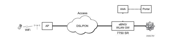 Figure 143: WLAN-GW Functions on Existing BNG