|

|

|

|

|
| For feedback, use the following: |
| ipd_online_feedback@alcatel-lucent.com |
|
|
|
|
|
|
*A:ALA-48configmcast-mgmtmcast-info-plcy# info----------------------------------------------bundle "default" createexit----------------------------------------------*A:ALA-48configmcast-mgmtmcast-info-plcy#
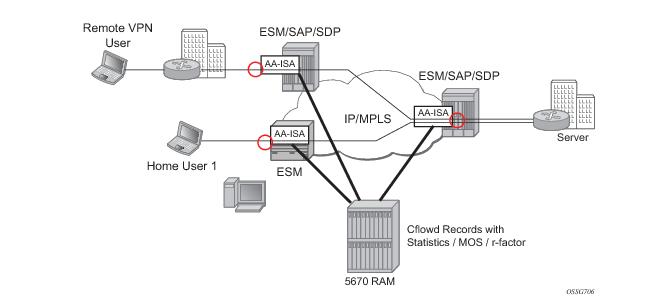
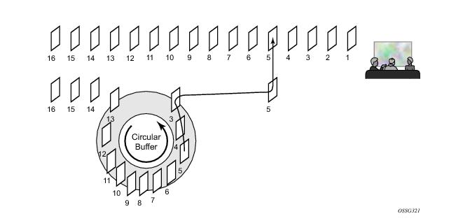
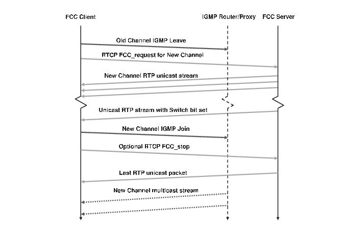
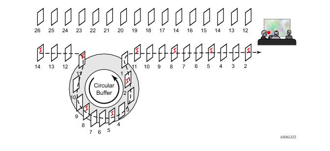
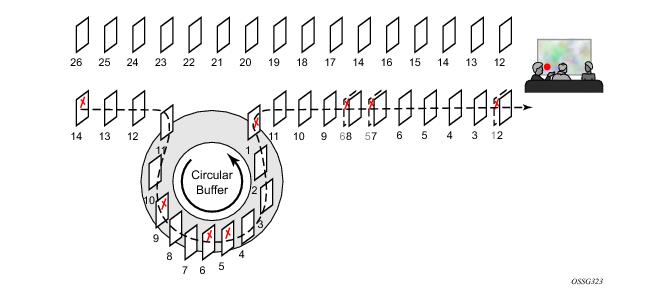
0 1 2 3Figure 31: RTP Header ExtensionB (Frame Begin Flag): set if a frame starts in this packetThe feature provides ability to measure and provide statistics to allow reporting on voice and video quality for VoIP and teleconferencing (A/V) applications. A sampled deployment is shown in the picture below (Figure 32). Although a distributed model is shown, a hub-and spoke model, with AA-ISA deployed only on one side of the traffic flow, is also supported.Figure 32: Voice/Video Monitoring Deployment ExampleRetransmission (RET) for RTP (RFC 3550, RTP: A Transport Protocol for Real-Time Applications) is based on a client/server model where the client sends negative acknowledgments (NACKs) using Real-time Transport Control Protocol (RTCP) (RFC 4585, Extended RTP Profile for Real-time Transport Control Protocol (RTCP)-Based Feedback (RTP/AVPF)) to a RET server when the client detects missing sequence numbers n the RTP stream. The RET server which caches the RTP stream, for example in a circular buffer, detects missing sequence numbers in the replies to the NACKs by resending the missing RTP packets as illustrated in Figure 33.Figure 33: RET Server Retransmission of a Missing FrameThe format of the reply must be agreed upon by the RET client and server and can be an exact copy (Payload Type 33 as defined in RFC 3551, RTP Profile for Audio and Video Conferences with Minimal Control ) or sent with a different Payload Type using an encapsulating RET header format (RFC 4588, RTP Retransmission Payload Format).Figure 34 illustrates the FCC client and server communication.Figure 34: FCC Client/Server ProtocolFigure 35: FCC Bursting Sent Faster Than Nominal RateFigure 36: FCC Denting Removing Less Important Frames
(S, G) → CHANNEL1_South (S2, G2)
→ CHANNEL1_East (S3, G3)
→ CHANNEL1_West (S4, G4)
→ CHANNEL1_Central (S5, G5)