For feedback and comments:
documentation.feedback@alcatel-lucent.com

Table of Contents Previous Next PDF


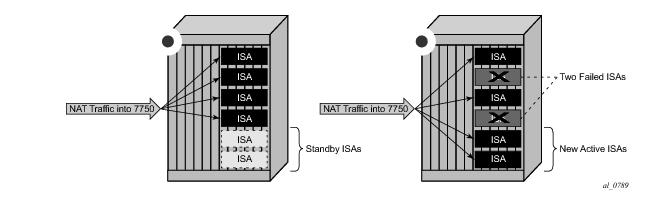
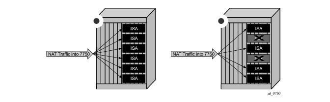
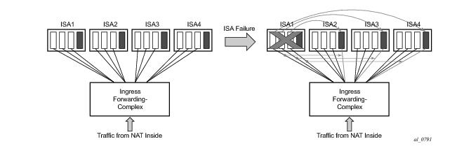
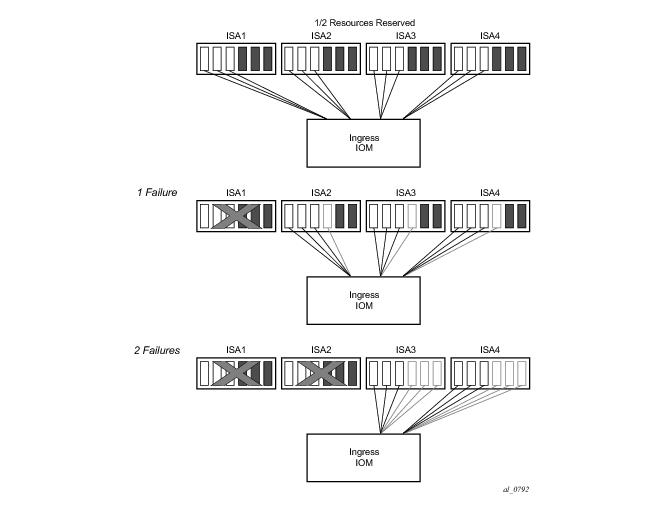
3. Configure the upnp-policy as created in Step 2 in the subscriber profile:
 
config>subscr-mgmt
        sub-profile "l2nat-upnp" create
            nat-policy "l2"
            upnp-policy "test"
        exit
 
NAT ISA (Intra-Chassis) Redundancy
NAT ISA redundancy helps protect against Integrated Service Adapter (ISA) failures. This protection mechanism relies on the CPM maintaining configuration copy of each ISA. In case that an ISA fails, the CPM restores the NAT configuration from the failed ISA to the remaining ISAs in the system. NAT configuration copy of each ISA, as maintained by CPM, is concerned with configuration of outside IP address and port forwards on each ISA. However, CPM does not maintain the state of dynamically created translations on each ISA. This will cause interruption in traffic until the translation are re-initiated by the devices behind the NAT.
Two modes of operation are supported:
Figure 66: Active-Standby Intra-Chassis Redundancy Model
By reserving memory resources it can be assured that failed traffic can be recovered by remaining ISAs, potentially with some bandwidth reduction in case that remaining ISAs operated at full or close to full speed before the failure occurred. Active-active ISA redundancy model is shown in Figure 67.
Figure 67: Active-Active Intra-Chassis Redundancy Model
In case of an ISA failure, the member-id of the member ISA that failed is contained in the FREE log. This info is used to find the corresponding MAP log which also contains the member-id field.
In case of RADIUS logging, CPM summarization trap is generated (since RADIUS log is sent from the ISA – which is failed).
 
Active-Active ISA Redundancy Model
In active-active ISA redundancy, each ISA is subdivided into multiple logical ISAs. These logical sub-entities are referred to as members. NAT configuration of each member is saved in the CPM. In case that any one ISA fails, its members will be downloaded by the CPM to the remaining active ISAs. Memory resources on each ISA will be reserved in order to accommodate additional traffic from the failed ISAs. The amount of resources reserved per ISA will depend on the number of ISAs in the system and the number of simultaneously supported ISA failures. The number of simultaneous ISA failures per system is configurable. Memory reservation will affect NAT scale per ISA.
Traffic received on the inside will be forwarded by the ingress forwarding complex to a predetermined member ISAs for further NAT processing. Each ingress forwarding complex maintains an internal link per member. The number of these internal links will, among other factors, determine the maximum number of members per system and with this, the granularity of traffic distribution over remaining ISAs in case of an ISA failure. The segmentation of ISAs into members for a single failure scenario is shown in Figure 68. The protection mechanism in this example is designed to cover for one physical ISA failure. Each ISA is divided into four members. Three of those will carry traffic during normal operation, while the fourth one will have resources reserved to accommodate traffic from one of the members in case of failure. When an ISA failure occurs, three members will be delegated to the remaining ISAs. Each member from the failed ISA will be mapped to a corresponding reserved member on the remaining ISAs.
Figure 68: Load Distribution in Active-Active Intra-Chassis Redundancy Model
Active-active ISA redundancy model supports multiple failures simultaneously. The protection mechanism shown in Figure 69 is designed to protect against two simultaneous ISA failures. Just like in the previous case, each ISA is divided into six members, three of which are carrying traffic under normal circumstances while the remaining three members have reserved memory resources.
Figure 69: Multiple Failures
Table 20shows resource utilization for a single ISA failure in relation to the total number of ISAs in the system. The resource utilization will affect only scale of each ISA. However, bandwidth per ISA is not reserved and each ISA can operate at full speed at any given time (with or without failures).
 
Start-up Conditions
During the first five minutes of system boot-up or nat-group activation, the system behaves as if all ISAs are operational. Consequently, ISAs are segmented in its members according to the configured maximum number of supported failures.
Upon expiration of this initial five minute interval, the system is re-evaluated. In case that one of more ISAs are found in faulty state during re-evaluation, the members of the failed ISAs will be distributed to the remaining ISAs that are operational.
 
Recovery
Once a failed ISA is recovered, the system will automatically accept it and traffic will be assigned to it. Traffic that is moved to the recovered ISA will be interrupted.
 
Adding Additional ISAs in the ISA Group
Adding additional ISAs in an operational nat-group requires reconfiguration of the active mda-limit for the nat-group (or the failed mda-limit for that matter). This is only possible when nat-group is in an administratively shutdown state.