There are currently two IETF standards for the provisioning of Virtual Private Wire Services (VPWS). RFC 4447, Pseudowire Setup and Maintenance Using the Label Distribution Protocol (LDP), describes Label Distribution Protocol (LDP) VPWS, where VPWS pseudowires are signaled using LDP between Provider Edge (PE) Routers.
RFC 6624, Layer 2 Virtual Private Networks Using BGP for Auto-Discovery and Signaling, describes the use of Border Gateway Protocol (BGP) for signaling of pseudo-wires between such PEs.
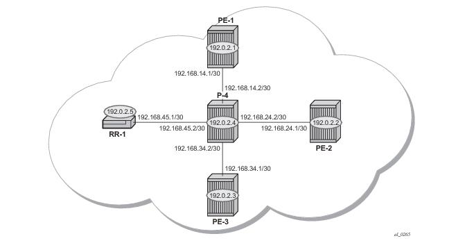
The network topology is displayed in Figure 39. The setup uses five Service Router (SR) nodes located in the same Autonomous System (AS). There are three PE routers connected to a single P router and a Route Reflector (RR-1) for the AS. The Provider Edge routers are all BGP VPWS aware. The Provider (P) router is BGP VPWS unaware and also does not take part in the BGP process.
configure router
autonomous-system 65536
bgp
group internal
family l2-vpn
type internal
peer-as 65536
local-as 65536
neighbor 192.0.2.5
exit
exit
no shutdown
exit
exit
configure router
autonomous-system 65536
bgp
group internal
type internal
cluster 1.1.1.1
family l2-vpn
peer-as 65536
local-as 65536
neighbor 192.0.2.1
exit
neighbor 192.0.2.2
exit
neighbor 192.0.2.3
exit
no shutdown
exit
exit
exit
A:RR-1# show router bgp summary
===============================================================================
BGP Router ID:192.0.2.5 AS:65536 Local AS:65536
===============================================================================
BGP Admin State : Up BGP Oper State : Up
Total Peer Groups : 1 Total Peers : 3
Total BGP Paths : 20 Total Path Memory : 3840
Total IPv4 Remote Rts : 0 Total IPv4 Rem. Active Rts : 0
Total McIPv4 Remote Rts : 0 Total McIPv4 Rem. Active Rts: 0
Total McIPv6 Remote Rts : 0 Total McIPv6 Rem. Active Rts: 0
Total IPv6 Remote Rts : 0 Total IPv6 Rem. Active Rts : 0
Total IPv4 Backup Rts : 0 Total IPv6 Backup Rts : 0
Total Supressed Rts : 0 Total Hist. Rts : 0
Total Decay Rts : 0
Total VPN Peer Groups : 0 Total VPN Peers : 0
Total VPN Local Rts : 0
Total VPN-IPv4 Rem. Rts : 0 Total VPN-IPv4 Rem. Act. Rts: 0
Total VPN-IPv6 Rem. Rts : 0 Total VPN-IPv6 Rem. Act. Rts: 0
Total VPN-IPv4 Bkup Rts : 0 Total VPN-IPv6 Bkup Rts : 0
Total VPN Supp. Rts : 0 Total VPN Hist. Rts : 0
Total VPN Decay Rts : 0
Total L2-VPN Rem. Rts : 16 Total L2VPN Rem. Act. Rts : 0
Total MVPN-IPv4 Rem Rts : 0 Total MVPN-IPv4 Rem Act Rts : 0
Total MDT-SAFI Rem Rts : 0 Total MDT-SAFI Rem Act Rts : 0
Total MSPW Rem Rts : 0 Total MSPW Rem Act Rts : 0
Total RouteTgt Rem Rts : 0 Total RouteTgt Rem Act Rts : 0
Total McVpnIPv4 Rem Rts : 0 Total McVpnIPv4 Rem Act Rts : 0
Total MVPN-IPv6 Rem Rts : 0 Total MVPN-IPv6 Rem Act Rts : 0
Total EVPN Rem Rts : 0 Total EVPN Rem Act Rts : 0
Total FlowIpv4 Rem Rts : 0 Total FlowIpv4 Rem Act Rts : 0
Total FlowIpv6 Rem Rts : 0 Total FlowIpv6 Rem Act Rts : 0
===============================================================================
BGP Summary
===============================================================================
Neighbor
AS PktRcvd InQ Up/Down State|Rcv/Act/Sent (Addr Family)
PktSent OutQ
-------------------------------------------------------------------------------
192.0.2.1
65536 58 0 00h21m05s 6/0/16 (L2VPN)
79 0
192.0.2.2
65536 50 0 00h20m06s 4/0/16 (L2VPN)
63 0
192.0.2.3
65536 60 0 00h21m33s 6/0/16 (L2VPN)
84 0
-------------------------------------------------------------------------------
A:RR-1#
config
service
[no] pw-template policy-id [use-provisioned-sdp] [create]
accounting-policy acct-policy-id
no accounting-policy
[no] collect-stats
egress
filter ipv6 ipv6-filter-id
filter ip ip-filter-id
filter mac mac-filter-id
no filter [ip ip-filter-id] [mac mac-filter-id] [ipv6 ipv6-filter-id]
qos network-policy-id port-redirect-group queue-group-name [instance instance-id]
no qos
[no] force-vlan-vc-forwarding
hash-label [signal-capability]
no hash-label
ingress
filter ipv6 ipv6-filter-id
filter ip ip-filter-id
filter mac mac-filter-id
no filter [ip ip-filter-id] [mac mac-filter-id] [ipv6 ipv6-filter-id]
qos network-policy-id fp-redirect-group queue-group-name instance instance-id
no qos
[no] sdp-exclude group-name
[no] sdp-include group-name
vc-type {ether | vlan}
vlan-vc-tag 0..4094
no vlan-vc-tag
|
•
|
The force-vlan-vc-forwarding function will add a tag (equivalent to vc-type vlan) and will allow for customer QoS transparency (dot1p+DE bits).
|
*A:PE-1# configure service pw-template
- [no] pw-template <policy-id> [use-provisioned-sdp] [create]
A:PE-1# configure router ldp
interface-parameters
interface "PE-1-P-4"
exit
targeted-session
exit
no shutdown
A:PE-1# configure service
pw-template 1 create
exit
A:PE-1# configure router mpls
interface "system"
no shutdown
            exit
            interface "PE-1-P-4"
no shutdown
exit
path "dyn"
no shutdown
exit
lsp "LSP-PE-1-PE-2"
to 192.0.2.2
primary "dyn"
exit
no shutdown
exit
lsp "LSP-PE-1-PE-3"
to 192.0.2.3
primary "dyn"
exit
no shutdown
exit
no shutdown
exit
A:PE-1# configure service sdp 12 mpls create
description "from-PE1"
far-end 192.0.2.2
            lsp "LSP-PE-1-PE-2"
            signaling bgp
keep-alive
shutdown
exit
no shutdown
Note that the signaling bgp parameter is required. BGP VPWS instances using BGP VPWS signaling are able to use these SDPs. Conversely, SDPs that are bound to RSVP-based LSPs with signaling set to the default value of “tldp” will not be used as SDPs within BGP VPWS.
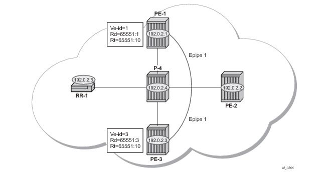
Figure 40 shows a schematic of a single homed BGP VPWS between PE-1 and PE-2 where SDPs are auto-provisioned. In this case, the transport tunnels are LDP signaled.
A:PE-1# configure service
pw-template 1 create
vc-type vlan
exit
epipe 1 customer 1 create
bgp
route-distinguisher 65551:1
route-target export target:65551:10 import target:65551:10
pw-template-binding 1
        exit
    exit
bgp-vpws
ve-name "PE1"
ve-id 1
exit
remote-ve-name "PE3"
ve-id 3
exit
            no shutdown
        exit
sap 1/1/4:100 create
exit
no shutdown
        exit
    exit
The bgp context specifies parameters that are required for BGP VPWS.
Within the bgp context, parameters are configured that are used by the neighboring PEs to determine the membership of a given BGP VPWS; in other words, the auto-discovery of PEs in the same BGP VPWS, the route-distinguisher is configured, along with the route target extended communities. Route target communities are used to determine membership of a given BGP VPWS. Note that the import and export route targets at the BGP level are mandatory. The pw-template binding is then applied and its parameters are used for both the routes sent by this PE and the received routes matching the route target value.
Within the bgp-vpws context, the signaling parameters are also configured. These determine the service labels required for the data plane of the VPWS instance.
It is also worth noting that changes to the pseudowire template are not taken into account once the pseudowire has been set up (changes of route-target are refreshed though). PW-templates can be re-evaluated with the tools perform eval-pw-template command. The
eval-pw-template checks if all of the bindings using this pw-template policy are still meant to be used this policy. If the template has changed and allow-service-impact is TRUE, then the old binding is removed and it is re-added using the new template.
pw-template 1 create
vc-type vlan
exit
epipe 1 customer 1 create
bgp
route-distinguisher 65551:3
route-target export target:65551:10 import target:65551:10
pw-template-binding 1
exit
exit
bgp-vpws
ve-name "PE3"
ve-id 3
exit
remote-ve-name "PE1"
ve-id 1
exit
no shutdown
exit
sap 1/1/4:101 create
exit
no shutdown
exit
exit
*A:PE-1# show service id 1 bgp-vpws
===============================================================================
BGP VPWS Information
===============================================================================
Admin State : Enabled
VE Name : PE1 VE Id : 1
PW Tmpl used : 1
Remote-Ve Information
-------------------------------------------------------------------------------
Remote VE Name : PE3 Remote VE Id : 3
===============================================================================
*A:PE-1
*A:PE-1# show service id 1 bgp
===============================================================================
BGP Information
===============================================================================
Route Dist : 65551:1
Rte-Target Import : 65551:10 Rte-Target Export: 65551:10
PW-Template Id : 1
Import Rte-Tgt : None
-------------------------------------------------------------------------------
===============================================================================
*A:PE-1#
*A:PE-1# show service id 1 base
===============================================================================
Service Basic Information
===============================================================================
Service Id : 1 Vpn Id : 0
Service Type : Epipe
Name : (Not Specified)
Description : (Not Specified)
Customer Id : 1 Creation Origin : manual
Last Status Change: 03/10/2014 10:08:06
Last Mgmt Change : 03/10/2014 10:08:06
Admin State : Up Oper State : Up
MTU : 1514
Vc Switching : False
SAP Count : 1 SDP Bind Count : 1
Per Svc Hashing : Disabled
Force QTag Fwd : Disabled
-------------------------------------------------------------------------------
Service Access & Destination Points
-------------------------------------------------------------------------------
Identifier Type AdmMTU OprMTU Adm Opr
-------------------------------------------------------------------------------
sap:1/1/4:100 q-tag 1578 1578 Up Up
sdp:17407:4294967295 SB(192.0.2.3) BgpVpws 0 1552 Up Up
===============================================================================
*A:PE-1#
*A:PE-1# show service id 1 sdp
===============================================================================
Services: Service Destination Points
===============================================================================
SdpId Type Far End addr Adm Opr I.Lbl E.Lbl
-------------------------------------------------------------------------------
17407:4294967295 BVws 192.0.2.3 Up Up 262141 262142
-------------------------------------------------------------------------------
Number of SDPs : 1
-------------------------------------------------------------------------------
===============================================================================
*A:PE-1#
170 2014/02/19 12:49:16.82 UTC MINOR: DEBUG #2001 Base Peer 1: 192.0.2.5
"Peer 1: 192.0.2.5: UPDATE
Peer 1: 192.0.2.5 - Send BGP UPDATE:
Withdrawn Length = 0
Total Path Attr Length = 76
Flag: 0x90 Type: 14 Len: 32 Multiprotocol Reachable NLRI:
Address Family L2VPN
NextHop len 4 NextHop 192.0.2.1
[VPLS/VPWS] veid: 1, vbo: 3, vbs: 1, label-base: 262131, RD 65551:1, csv
: 0x0
Flag: 0x40 Type: 1 Len: 1 Origin: 0
Flag: 0x40 Type: 2 Len: 0 AS Path:
Flag: 0x80 Type: 4 Len: 4 MED: 0
Flag: 0x40 Type: 5 Len: 4 Local Preference: 100
Flag: 0xc0 Type: 16 Len: 16 Extended Community:
target:65551:10
l2-vpn/vrf-imp:Encap=4: Flags=none: MTU=1514: PREF=0
"
193 2014/02/19 13:22:10.61 UTC MINOR: DEBUG #2001 Base Peer 1: 192.0.2.5
"Peer 1: 192.0.2.5: UPDATE
Peer 1: 192.0.2.5 - Received BGP UPDATE:
Withdrawn Length = 0
Total Path Attr Length = 90
Flag: 0x90 Type: 14 Len: 32 Multiprotocol Reachable NLRI:
Address Family L2VPN
NextHop len 4 NextHop 192.0.2.1
[VPLS/VPWS] veid: 1, vbo: 3, vbs: 1, label-base: 262131, RD 65551:1, csv
: 0x80
Flag: 0x40 Type: 1 Len: 1 Origin: 0
Flag: 0x40 Type: 2 Len: 0 AS Path:
Flag: 0x80 Type: 4 Len: 4 MED: 0
Flag: 0x40 Type: 5 Len: 4 Local Preference: 100
Flag: 0x80 Type: 9 Len: 4 Originator ID: 192.0.2.1
Flag: 0x80 Type: 10 Len: 4 Cluster ID:
1.1.1.1
Flag: 0xc0 Type: 16 Len: 16 Extended Community:
target:65551:10
l2-vpn/vrf-imp:Encap=4: Flags=D: MTU=1514: PREF=0
"
*A:PE-1# show service l2-route-table bgp-vpws detail
===============================================================================
Services: L2 Bgp-Vpws Route Information - Summary
===============================================================================
Svc Id : 1
VeId : 3
PW Temp Id : 1
RD : *65551:3
Next Hop : 192.0.2.3
State (D-Bit) : up(0)
Path MTU : 1514
Control Word : 0
Seq Delivery : 0
Status : active
Tx Status : active
CSV : 0
Preference : 0
Sdp Bind Id : 17407:4294967295
<snipped>
*A:PE-1#
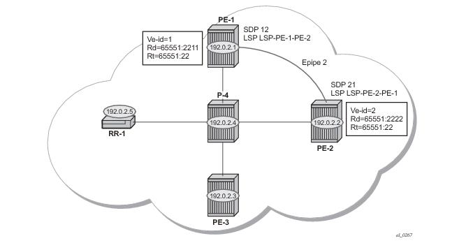
Figure 41 shows a schematic of a BGP VPWS where SDPs are pre-provisioned with RSVP-TE signaled transport tunnels.
configure service
sdp 12 mpls create
description "from-192.0.2.1"
signaling bgp
far-end 192.0.2.2
lsp "LSP-PE-1-PE-2"
keep-alive
shutdown
exit
no shutdown
exit
exit
configure service
sdp 21 mpls create
description "from-192.0.2.2"
signaling bgp
far-end 192.0.2.1
lsp "LSP-PE-2-PE-1"
keep-alive
shutdown
exit
no shutdown
exit
exit
A:PE-1# configure service
pw-template 2 use-provisioned-sdp create
vc-type ether
exit
A:PE-1# configure service epipe 2 customer 1 create
bgp
route-distinguisher 65551:2211
route-target export target:65551:22 import target:65551:22
pw-template-binding 2
exit
exit
bgp-vpws
ve-name "PE-1"
ve-id 1
exit
remote-ve-name "PE-2"
ve-id 2
exit
no shutdown
exit
sap 1/1/4:2200 create
exit
no shutdown
exit
exit
A:PE-2# configure service epipe 2 customer 1 create
bgp
route-distinguisher 65551:2222
route-target export target:65551:22 import target:65551:22
pw-template-binding 2
exit
exit
bgp-vpws
ve-name "PE2"
ve-id 2
exit
remote-ve-name "PE-1"
ve-id 1
exit
no shutdown
exit
sap 1/1/4:200 create
exit
no shutdown
exit
*A:PE-1# show service id 2 base
===============================================================================
Service Basic Information
===============================================================================
Service Id : 2 Vpn Id : 0
Service Type : Epipe
Name : (Not Specified)
Description : (Not Specified)
Customer Id : 1 Creation Origin : manual
Last Status Change: 03/10/2014 10:09:04
Last Mgmt Change : 03/10/2014 10:09:04
Admin State : Up Oper State : Up
MTU : 1514
Vc Switching : False
SAP Count : 1 SDP Bind Count : 1
Per Svc Hashing : Disabled
Force QTag Fwd : Disabled
-------------------------------------------------------------------------------
Service Access & Destination Points
-------------------------------------------------------------------------------
Identifier Type AdmMTU OprMTU Adm Opr
-------------------------------------------------------------------------------
sap:1/1/4:2200 q-tag 1578 1578 Up Up
sdp:12:4294967292 S(192.0.2.2) BgpVpws 0 1552 Up Up
===============================================================================
*A:PE-1#
A:PE-2# show service id 2 base
===============================================================================
Service Basic Information
===============================================================================
Service Id : 2 Vpn Id : 0
Service Type : Epipe
Name : (Not Specified)
Description : (Not Specified)
Customer Id : 1 Creation Origin : manual
Last Status Change: 03/10/2014 12:06:37
Last Mgmt Change : 03/10/2014 12:06:37
Admin State : Up Oper State : Up
MTU : 1514
Vc Switching : False
SAP Count : 1 SDP Bind Count : 1
Per Svc Hashing : Disabled
Force QTag Fwd : Disabled
-------------------------------------------------------------------------------
Service Access & Destination Points
-------------------------------------------------------------------------------
Identifier Type AdmMTU OprMTU Adm Opr
-------------------------------------------------------------------------------
sap:1/1/4:200 q-tag 1578 1578 Up Up
sdp:21:4294967293 S(192.0.2.1) BgpVpws 0 1552 Up Up
===============================================================================
A:PE-2#
For access redundancy, an Epipe using a BGP VPWS service can be configured as dual-homed, as described in draft-ietf-l2vpn-vpls-multihoming-03. It can be configured with a single pseudowire setup, where the redundant pseudowire is not created until the initially active pseudowire is removed.
A:PE-1# configure service
pw-template 3 create
exit
epipe 3 customer 1 create
bgp
route-distinguisher 65551:31
route-target export target:65551:31 import target:65551:31
pw-template-binding 3
exit
exit
bgp-vpws
ve-name "PE-1"
ve-id 1
exit
remote-ve-name "PE-2"
ve-id 2
exit
no shutdown
exit
site "siteB" create
site-id 1
sap 1/1/4:99
site-preference 200
no shutdown
exit
sap 1/1/4:99 create
exit
no shutdown
exit
exit
A:PE-3# configure service
pw-template 3 create
exit
epipe 3 customer 1 create
bgp
route-distinguisher 65551:33
route-target export target:65551:31 import target:65551:31
pw-template-binding 3
exit
exit
bgp-vpws
ve-name "PE-3"
ve-id 1
exit
remote-ve-name "PE-2"
ve-id 2
exit
no shutdown
exit
site "siteB" create
site-id 1
sap 1/1/4:99
site-preference 10
no shutdown
exit
sap 1/1/4:99 create
exit
no shutdown
exit
exit
A:PE-2# configure service
pw-template 3 create
exit
epipe 3 customer 1 create
bgp
route-distinguisher 65551:32
route-target export target:65551:31 import target:65551:31
pw-template-binding 3
exit
exit
bgp-vpws
ve-name "PE-2"
ve-id 2
exit
remote-ve-name "PE-1orPE-3"
ve-id 1
exit
no shutdown
exit
sap 1/1/4:99 create
exit
no shutdown
exit
exit
*A:PE-2# show router bgp routes l2-vpn rd 65551:31
===============================================================================
BGP Router ID:192.0.2.2 AS:65536 Local AS:65536
===============================================================================
Legend -
Status codes : u - used, s - suppressed, h - history, d - decayed, * - valid
Origin codes : i - IGP, e - EGP, ? - incomplete, > - best, b - backup
===============================================================================
BGP L2VPN Routes
===============================================================================
Flag RouteType Prefix MED
RD SiteId Label
Nexthop VeId BlockSize LocalPref
As-Path BaseOffset vplsLabelBa
se
-------------------------------------------------------------------------------
u*>i MultiHome - - 0
65551:31 1 -
192.0.2.1 - - 200
No As-Path - -
u*>i VPWS - - 0
65551:31 - -
192.0.2.1 1 1 200
No As-Path 2 262139
-------------------------------------------------------------------------------
Routes : 2
===============================================================================
*A:PE-2#
*A:PE-2# show router bgp routes l2-vpn rd 65551:33
===============================================================================
BGP Router ID:192.0.2.2 AS:65536 Local AS:65536
===============================================================================
Legend -
Status codes : u - used, s - suppressed, h - history, d - decayed, * - valid
Origin codes : i - IGP, e - EGP, ? - incomplete, > - best, b - backup
===============================================================================
BGP L2VPN Routes
===============================================================================
Flag RouteType Prefix MED
RD SiteId Label
Nexthop VeId BlockSize LocalPref
As-Path BaseOffset vplsLabelBa
se
-------------------------------------------------------------------------------
u*>i MultiHome - - 0
65551:33 1 -
192.0.2.3 - - 10
No As-Path - -
u*>i VPWS - - 0
65551:33 - -
192.0.2.3 1 1 10
No As-Path 2 262140
-------------------------------------------------------------------------------
Routes : 2
===============================================================================
*A:PE-2#
A:PE-2# show service l2-route-table bgp-vpws detail
===============================================================================
Services: L2 Bgp-Vpws Route Information - Summary
===============================================================================
<snipped>
Svc Id : 3
VeId : 1
PW Temp Id : 3
RD : *65551:31
Next Hop : 192.0.2.1
State (D-Bit) : up(0)
Path MTU : 1514
Control Word : 0
Seq Delivery : 0
Status : active
Tx Status : active
CSV : 0
Preference : 200
Sdp Bind Id : 17407:4294967295
<snipped>
===============================================================================
*A:PE-2#
240 2014/02/19 15:08:15.65 UTC MINOR: DEBUG #2001 Base Peer 1: 192.0.2.5
"Peer 1: 192.0.2.5: UPDATE
Peer 1: 192.0.2.5 - Received BGP UPDATE:
Withdrawn Length = 0
Total Path Attr Length = 86
Flag: 0x90 Type: 14 Len: 28 Multiprotocol Reachable NLRI:
Address Family L2VPN
NextHop len 4 NextHop 192.0.2.1
[MH] site-id: 1, RD 65551:31
Flag: 0x40 Type: 1 Len: 1 Origin: 0
Flag: 0x40 Type: 2 Len: 0 AS Path:
Flag: 0x80 Type: 4 Len: 4 MED: 0
Flag: 0x40 Type: 5 Len: 4 Local Preference: 0
Flag: 0x80 Type: 9 Len: 4 Originator ID: 192.0.2.1
Flag: 0x80 Type: 10 Len: 4 Cluster ID:
1.1.1.1
Flag: 0xc0 Type: 16 Len: 16 Extended Community:
target:65551:31
l2-vpn/vrf-imp:Encap=19: Flags=D: MTU=0: PREF=200
"
241 2014/02/19 15:08:15.64 UTC MINOR: DEBUG #2001 Base Peer 1: 192.0.2.5
"Peer 1: 192.0.2.5: UPDATE
Peer 1: 192.0.2.5 - Received BGP UPDATE:
Withdrawn Length = 0
Total Path Attr Length = 90
Flag: 0x90 Type: 14 Len: 32 Multiprotocol Reachable NLRI:
Address Family L2VPN
NextHop len 4 NextHop 192.0.2.1
[VPLS/VPWS] veid: 1, vbo: 2, vbs: 1, label-base: 262139, RD 65551:31, cs v: 0x80
Flag: 0x40 Type: 1 Len: 1 Origin: 0
Flag: 0x40 Type: 2 Len: 0 AS Path:
Flag: 0x80 Type: 4 Len: 4 MED: 0
Flag: 0x40 Type: 5 Len: 4 Local Preference: 0
Flag: 0x80 Type: 9 Len: 4 Originator ID: 192.0.2.1
Flag: 0x80 Type: 10 Len: 4 Cluster ID:
1.1.1.1
Flag: 0xc0 Type: 16 Len: 16 Extended Community:
target:65551:31
l2-vpn/vrf-imp:Encap=5: Flags=D: MTU=1514: PREF=200
""
A:PE-2# show service l2-route-table bgp-vpws detail
===============================================================================
Services: L2 Bgp-Vpws Route Information - Summary
===============================================================================
Svc Id : 3
VeId : 1
PW Temp Id : 3
RD : *65551:33
Next Hop : 192.0.2.3
State (D-Bit) : up(0)
Path MTU : 1514
Control Word : 0
Seq Delivery : 0
Status : active
Tx Status : active
CSV : 0
Preference : 200
Sdp Bind Id : 17407:4294967295
===============================================================================
A:PE-2#
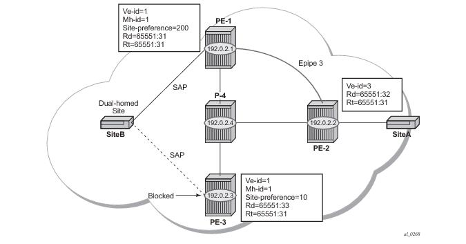
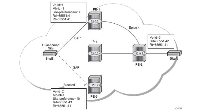
Figure 43 shows a setup where an Epipe is configured on each PE. Site B is dual-homed to PE-1 and PE-3 with the remote PE-2 connected to site A; each site connection uses a SAP. The active/standby pseudowires using Ethernet Raw Mode encapsulation connect PE-2 to PE-1 and PE-3. The pseudowires are signaled using BGP VPWS over tunnel LSPs between the PEs.
A:PE-1# configure service
pw-template 3 create
exit
epipe 4 customer 1 create
bgp
route-distinguisher 65551:41
route-target export target:65551:41 import target:65551:41
pw-template-binding 3
exit
exit
bgp-vpws
ve-name "PE-1"
ve-id 1
exit
remote-ve-name "PE-2"
ve-id 2
exit
no shutdown
exit
site "siteB" create
site-id 1
sap 1/1/4:44
site-preference 200
no shutdown
exit
sap 1/1/4:44 create
exit
no shutdown
exit
exit
A:PE-3# configure service
pw-template 3 create
exit
epipe 4 customer 1 create
bgp
route-distinguisher 65551:43
route-target export target:65551:41 import target:65551:41
pw-template-binding 3
exit
exit
bgp-vpws
ve-name "PE-3"
ve-id 3
exit
remote-ve-name "PE-2"
ve-id 2
exit
no shutdown
exit
site "siteB" create
site-id 1
sap 1/1/4:44
site-preference 10
no shutdown
exit
sap 1/1/4:44 create
exit
no shutdown
exit
exit
A:PE-2# configure service
pw-template 3 create
exit
epipe 4 customer 1 create
bgp
route-distinguisher 65551:42
route-target export target:65551:41 import target:65551:41
pw-template-binding 3
exit
exit
bgp-vpws
ve-name "PE-2"
ve-id 2
exit
remote-ve-name "PE-1"
ve-id 1
exit
remote-ve-name "PE-3"
ve-id 3
exit
no shutdown
exit
sap 1/1/4:44 create
exit
no shutdown
exit
exit
A:PE-2# show service l2-route-table bgp-vpws detail
===============================================================================
Services: L2 Bgp-Vpws Route Information - Summary
===============================================================================
<snipped>
Svc Id : 4
VeId : 1
PW Temp Id : 3
RD : *65551:41
Next Hop : 192.0.2.1
State (D-Bit) : up(0)
Path MTU : 1514
Control Word : 0
Seq Delivery : 0
Status : active
Tx Status : active
CSV : 0
Preference : 200
Sdp Bind Id : 17407:4294967294
Svc Id : 4
VeId : 3
PW Temp Id : 3
RD : *65551:43
Next Hop : 192.0.2.3
State (D-Bit) : up(0)
Path MTU : 1514
Control Word : 0
Seq Delivery : 0
Status : active
Tx Status : inactive
CSV : 0
Preference : 10
Sdp Bind Id : 17406:4294967292
===============================================================================
A:PE-2#
A:PE-2# show service id 4 endpoint
===============================================================================
Service 4 endpoints
===============================================================================
Endpoint name : _tmnx_BgpVpws-4
Description : Automatically created BGP-VPWS endpoint
Creation Origin : bgpVpws
Revert time : 0
Act Hold Delay : 0
Standby Signaling Master : false
Standby Signaling Slave : false
Tx Active (SDP) : 17407:4294967294
Tx Active Up Time : 0d 00:24:26
Revert Time Count Down : N/A
Tx Active Change Count : 1
Last Tx Active Change : 03/10/2014 12:06:37
-------------------------------------------------------------------------------
Members
-------------------------------------------------------------------------------
Spoke-sdp: 17406:4294967292 Prec:4 Oper Status: Up
Spoke-sdp: 17407:4294967294 Prec:4 Oper Status: Up
===============================================================================
===============================================================================
A:PE-2#
tools perform service id <service-id> endpoint <endpoint-name> force-switchover