Beginning with SR OS 8.0R1, the SR/ESS portfolio supports the use of Border Gateway Protocol Multi-Homing for VPLS (hereafter called BGP-MH). BGP-MH is described in draft-ietf-l2vpn-vpls-multihoming, BGP based Multi-homing in Virtual Private LAN Service, and provides a network-based resiliency mechanism (no interaction from the PEs Provider Edge router — to MTU/CEs Multi-tenant Unit/Customer Equipment) that can be applied on access Service Access Points (SAPs) or network (pseudowires) topologies. The BGP-MH procedures will run between the PEs and will provide a loop-free topology from the network perspective (only one logical active path will be provided per VPLS among all the objects SAPs or pseudowires which are part of the same Multi-Homing site).
Knowledge of the LDP/BGP VPLS (RFC 4762, Virtual Private LAN Service (VPLS) Using Label Distribution Protocol (LDP) Signaling, and RFC 4761,
Virtual Private LAN Service (VPLS) Using BGP for Auto-Discovery and Signaling) architecture and functionality is assumed throughout this document. For further information refer to the relevant Alcatel-Lucent documentation.
|
•
|
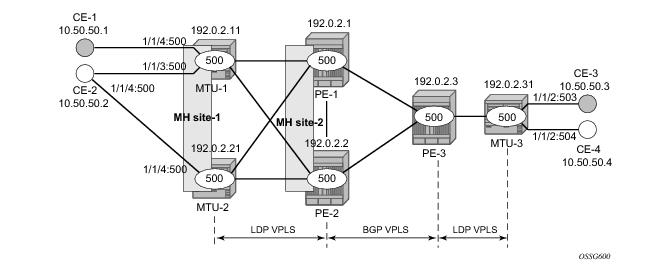
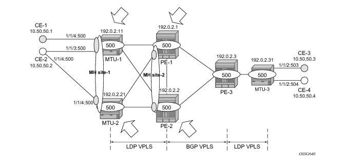
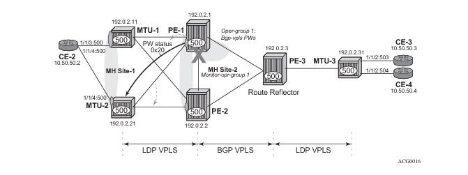
As depicted in the Figure 31, the MTUs are connected to the BGP VPLS core by TLDP pseudowires. While MTU-3 is connected to PE-3 by a single pseudowire, MTU-1 and MTU-2 are dual-homed to PE-1 and PE-2. The following resiliency mechanisms are used on the dual-homed MTUs:
|
A direct peering is established between MTU-1 and MTU-2 for use c. Note that the same RR could have been used for the three cases, however, like in this example, the designer may choose to have a direct BGP peering between access devices. The reasons for this are:
A:MTU-1>config>router# info
----------------------------------------------
...
autonomous-system 65000
router-id 192.0.2.11
...
bgp
group "Multi-homing"
neighbor 192.0.2.21
type internal
peer-as 65000
exit
exit
exit
A:PE-3>config>router# info
----------------------------------------------
...
bgp
group "internal"
cluster 1.1.1.1
neighbor 192.0.2.1
type internal
peer-as 65000
exit
neighbor 192.0.2.2
type internal
peer-as 65000
exit
exit
exit
...
|
•
|
It is required to specify family l2-vpn in the BGP configuration. That statement will allow the BGP peers to agree on the support for the family AFI=25 (Layer 2 VPN), SAFI=65 (VPLS). This family is used for BGP VPLS as well as for BGP MH and BGP AD.
|
|
•
|
The rapid-update l2-vpn statement allows BGP MH to send BGP updates immediately after detecting link failures, without having to wait for the MRAI to send the updates in batches. This statement is required to guarantee a fast convergence for BGP MH.
|
|
•
|
Optionally, rapid-withdrawal can also be added. Note that, in the context of BGP MH, this command is only useful if a particular multi-homing site is cleared 2. In that case, a BGP withdrawal is sent immediately without having to wait for the MRAI. |
A:PE-1>config>service# info
----------------------------------------------
...
sdp 111 mpls create
far-end 192.0.2.11
lsp "LSP-PE-1-MTU-1"
path-mtu 8000
keep-alive
shutdown
exit
no shutdown
exit
sdp 121 mpls create
far-end 192.0.2.21
lsp "LSP-PE-1-MTU-2"
path-mtu 8000
keep-alive
shutdown
exit
no shutdown
exit
sdp 1212 mpls create
far-end 192.0.2.2
lsp "LSP-PE-1-PE-2"
signaling bgp # this sdp will transport BGP-signaled pseudowires
path-mtu 8000
keep-alive
shutdown
exit
no shutdown
exit
sdp 1313 mpls create
far-end 192.0.2.3
lsp LSP-PE-1-PE-3
signaling bgp # this sdp will transport BGP-signaled pseudowires
path-mtu 8000
keep-alive
shutdown
exit
no shutdown
exit
...
pw-template 500 use-provisioned-sdp create
exit
...
vpls 500 customer 1 create
split-horizon-group "CORE" create
exit
bgp # BGP context with common parameters for BGP VPLS and BGP MH
route-distinguisher 65000:501
vsi-export "vsi500_export"
vsi-import "vsi500_import"
pw-template-bind 500 split-horizon-group "CORE"
exit
bgp-vpls # Specific context for BGP VPLS configuration
max-ve-id 65535
ve-name 501
ve-id 501
exit
no shutdown
exit
stp
shutdown
exit
site "MH-site-2" create # BGP MH specific configuration
site-id 2
spoke-sdp 121:500
no shutdown
exit
spoke-sdp 111:500 create
exit
spoke-sdp 121:500 create
exit
no shutdown
exit
|
→
|
The pw-template-bind command maps the previously defined pw-template 500 to the split-horizon-group CORE. In this way, all the BGP-signalled pseudowires will be part of this split-horizon-group. Although not shown in this example, the pw-template-bind command can also be used to instantiate pseudowires within different split-horizon-groups, based on different import route-targets 3:
|
A:PE-1# configure service vpls 1 bgp pw-template-bind ?
- pw-template-bind <policy-id> [split-horizon-group <group-name>] [import-rt {ext-community, ...(upto 5 max)}]
- no pw-template-bind <policy-id>
*A:PE1> vpls <service-id> [customer <customer-id>][vpn <vpn-id>][m-vpls][b-vpls]
[no] site <site-name> [create] # 32 characters maximum
[no] site-id <site-id-value> # Range: 1..65535
[no] spoke-sdp sdp-id[:vc-id]
[no] sap <sap-id>
[no] split-horizon-group <group-name>
[no] mesh-sdp-binding
[no] failed-threshold <value|all> # Range:1-1000. Default: all
[no] boot-timer <interval> # Range:0-600. Default: 10
[no] site-activation-timer <interval> # Range:0-100. Default: 2
[no] shutdown
A:PE-1>config>service>vpls>site# mesh-sdp-binding
MINOR: SVCMGR #5855 only one object is allowed per site
|
•
|
The failed-threshold command defines how many objects should be down for the site to be declared down. This command is obviously only valid for multi-object sites (split-horizon-groups and mesh-sdp-bindings). By default, all the objects in a site must be down for the site to be declared as operationally down.
|
|
•
|
The boot-timer specifies for how long the service manager waits after a node reboot before running the MH Procedures. The boot-timer value should be configured to allow for the BGP sessions to come up and for the NLRI information to be refreshed/exchanged. In environments with the default BGP MRAI (30 seconds) it is highly recommended to increase this value (for instance, 120 seconds for a normal configuration). The boot-timer is only important when a node comes back up and would become the DF.
|
|
•
|
The site-activation-timer command defines the amount of time the service manager will keep the local objects in standby (in the absence of BGP updates from remote PEs) before running the DF election algorithm to decide whether the site should be unblocked. The timer is started when one of the following events occurs only if the site is operationally up:
|
|
•
|
The boot-timer and site-activation-timer commands can be provisioned at service level or at global level. The service level settings have precedence and override the global configuration. The no form of the commands at global level, sets the value back to the default values, (10 and 2 seconds, respectively). The no form of the commands at service level, makes the timers inherit the global values.
|
*A:PE-1# configure redundancy bgp-multi-homing
- bgp-multi-homing
[no] boot-timer - Configure BGP multi-homing boot-timer
[no] site-activatio* - Configure BGP multi-homing site activation timer
|
•
|
The shutdown command controls the ADMIN state of the site. Note that each site has three possible states:
|
*A:MTU-2# show service id 500 site "MH-site-1"
===============================================================================
Site Information
===============================================================================
Site Name : MH-site-1
-------------------------------------------------------------------------------
Site Id : 1
Dest : sap:1/1/4:500 Mesh-SDP Bind : no
DF UpTime : 0d 00:00:00 secs DF Chg Cnt : 1
Failed Threshold : default(all)
===============================================================================
A:PE-2>config>service# info
----------------------------------------------
...
sdp 211 mpls create
far-end 192.0.2.11
lsp "LSP-PE-2-MTU-1"
path-mtu 8000
keep-alive
shutdown
exit
no shutdown
exit
sdp 221 mpls create
far-end 192.0.2.21
lsp "LSP-PE-2-MTU-2"
path-mtu 8000
keep-alive
shutdown
exit
no shutdown
exit
sdp 2121 mpls create
far-end 192.0.2.1
lsp "LSP-PE-2-PE-1"
signaling bgp # this sdp will transport BGP-signaled pseudowires
path-mtu 8000
keep-alive
shutdown
exit
no shutdown
exit
sdp 2323 mpls create
far-end 192.0.2.3
lsp "LSP-PE-2-PE-3"
signaling bgp # this sdp will transport BGP-signaled pseudowires
path-mtu 8000
keep-alive
shutdown
exit
no shutdown
exit
...
pw-template 500 use-provisioned-sdp create
exit
...
vpls 500 customer 1 create
split-horizon-group "CORE" create
exit
bgp
route-distinguisher 65000:502
vsi-export "vsi500_export"
vsi-import "vsi500_import"
pw-template-bind 500 split-horizon-group "CORE"
exit
bgp-vpls
max-ve-id 65535
ve-name 502
ve-id 502
exit
no shutdown
exit
stp
shutdown
exit
site "MH-site-2" create
site-id 2
spoke-sdp 221:500
no shutdown
exit
spoke-sdp 211:500 create
exit
spoke-sdp 221:500 create
exit
no shutdown
exit
...
A:MTU-1>config>service# info
...
sdp 111 mpls create
far-end 192.0.2.1
lsp "LSP-MTU-1-PE-1"
path-mtu 8000
keep-alive
shutdown
exit
no shutdown
exit
sdp 112 mpls create
far-end 192.0.2.2
lsp "LSP-MTU-1-PE-2"
path-mtu 8000
keep-alive
shutdown
exit
no shutdown
exit
...
vpls 500 customer 1 create
split-horizon-group "site-1" create
exit
bgp
route-distinguisher 65000:511
route-target export target:65000:500 import target:65000:500
exit
stp
shutdown
exit
site "MH-site-1" create
site-id 1
split-horizon-group site-1
no shutdown
exit
endpoint "CORE" create
no suppress-standby-signaling
exit
sap 1/1/3:500 split-horizon-group "site-1" create
eth-cfm
mep 511 domain 1 association 1 direction down
fault-propagation-enable use-if-tlv
ccm-enable
no shutdown
exit
exit
exit
sap 1/1/4:500 split-horizon-group "site-1" create
exit
spoke-sdp 111:500 endpoint "CORE" create
stp
shutdown
exit
precedence primary
exit
spoke-sdp 112:500 endpoint "CORE" create
stp
shutdown
exit
exit
no shutdown
exit
A:MTU-2>config>service# info
...
sdp 211 mpls create
far-end 192.0.2.1
lsp "LSP-MTU-2-PE-1"
path-mtu 8000
keep-alive
shutdown
exit
no shutdown
exit
sdp 212 mpls create
far-end 192.0.2.2
lsp "LSP-MTU-2-PE-2"
path-mtu 8000
keep-alive
shutdown
exit
no shutdown
exit
...
vpls 500 customer 1 create
bgp
route-distinguisher 65000:521
route-target export target:65000:500 import target:65000:500
exit
stp
shutdown
exit
site "MH-site-1" create
site-id 1
sap 1/1/4:500
no shutdown
exit
sap 1/1/4:500 create
exit
spoke-sdp 211:500 create
exit
spoke-sdp 212:500 create
exit
no shutdown
exit
A:PE-2# admin display-config
...
#--------------------------------------------------
echo "Service Configuration"
#--------------------------------------------------
...
vpls 500 customer 1 create
...
bgp
route-distinguisher 65000:502
vsi-export "vsi500_export"
vsi-import "vsi500_import"
...
#--------------------------------------------------
echo "Policy Configuration"
#--------------------------------------------------
policy-options
begin
community "comm_core" members "target:65000:500"
policy-statement "vsi500_export"
entry 10
action accept
community add "comm_core"
local-preference 150
exit
exit
exit
policy-statement "vsi500_import"
entry 10
from
community "comm_core"
exit
action accept
exit
exit
default-action reject
exit
A:PE-1# admin display-config
...
#--------------------------------------------------
echo "Service Configuration"
#--------------------------------------------------
...
vpls 500 customer 1 create
...
bgp
route-distinguisher 65000:501
vsi-export "vsi500_export"
vsi-import "vsi500_import"
...
#--------------------------------------------------
echo "Policy Configuration"
#--------------------------------------------------
policy-options
begin
community "comm_core" members "target:65000:500"
policy-statement "vsi500_export"
entry 10
action accept
community add "comm_core"
exit
exit
exit
policy-statement "vsi500_import"
entry 10
from
community "comm_core"
exit
action accept
exit
exit
default-action reject
exit
|
•
|
Access PEs running BGP MH on spoke-sdps and elected non-DF, will signal pseudowire standby status (0x20) to the other end. If no pseudowire status is supported on the remote MTU, a label withdrawal is performed 4. If there is more than one spoke SDP on the site (part of the same SHG), the signaling is sent for all the pseudowires of the site. |
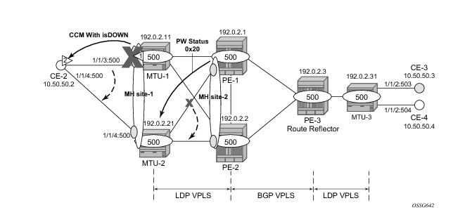
In this example, down MEPs on MTU-1 sap 1/1/3:500, sap 1/1/4:500 and MTU-2 sap 1/1/4:500 are configured. Figure 34 shows only the MEPs on MTU-1 sap 1/1/3:500 and CE-2. Upon failure on the MTU-1 site MH-site-1 the MEP 1 will start sending CCMs with interface status down.
The CFM configuration required at sap 1/1/3:500 is outlined below
5. Down MEPs will be configured on CE-2 and MTU-2 saps in the same way. Note that
fault-propagation-enable use-if-tlv must be added. In case the CE does not understand the CCM interface status TLV, the
fault-propagation-enable suspend-ccm option can be enabled instead. This will stop the transmission of CCMs upon site failures.
A:MTU-1>config>service# info
...
vpls 500 customer 1 create
split-horizon-group "site-1" create
exit
...
site "MH-site-1" create
site-id 1
split-horizon-group site-1
no shutdown
exit
...
sap 1/1/3:500 split-horizon-group "site-1" create
eth-cfm
mep 2 domain 1 association 1 direction down
fault-propagation-enable use-if-tlv
ccm-enable
no shutdown
exit
exit
exit
56 2010/02/06 15:18:00.62 UTC MINOR: ETH_CFM #2001 Base
"MEP 1/1/2 highest defect is now defMACstatus"
57 2010/02/06 15:18:00.63 UTC MINOR: SVCMGR #2108 vprn502
"Status of interface int-CE2-MTU-1 in service 500 (customer 1) changed to admin=up oper=down"
58 2010/02/06 15:18:00.63 UTC MINOR: SVCMGR #2203 vprn502
"Status of SAP 1/1/3:500 in service 500 (customer 1) changed to admin=up oper=down flags=OamDownMEPFault"
59 2010/02/06 15:18:00.63 UTC WARNING: SNMP #2004 vprn500 int-CE2-MTU-1
"Interface int-CE2-MTU-1 is not operational"
*A:CE-2# show service id 500 sap 1/1/3:500
===============================================================================
Service Access Points(SAP)
===============================================================================
Service Id : 500
SAP : 1/1/3:500 Encap : q-tag
Description : (Not Specified)
Admin State : Up Oper State : Down
Flags : OamDownMEPFault
Multi Svc Site : None
Last Status Change : 02/06/2010 15:18:01
Last Mgmt Change : 02/05/2010 12:21:26
===============================================================================
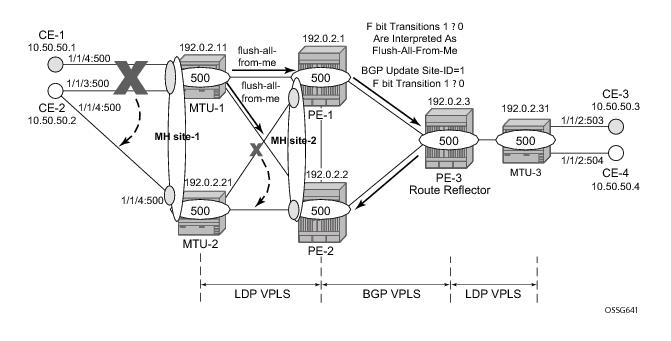
As also depicted in Figure 34, PE-1 will signal pseudowire status standby (code 0x20) when PE-1 goes to non-DF state for MH-site-2 MTU-2 will receive that signaling and, based on the
ignore-standby-signaling parameter, will decide whether to send the broadcast, unknown unicast and multicast (BUM) traffic to PE-1. In case MTU-2 uses in its configuration
ignore-standby-signaling. it will be sending BUM traffic on both pseudowires at the same time (which is not normally desired), ignoring the pseudowire status bits. The following output shows the MTU-2 spoke
sdp receiving the pseudowire status signaling. Note that although the spoke SDP stays operationally up, the peer Pw Bits field shows
pwFwdingStandby and MTU-2 will not send any traffic if the
ignore-standby-signaling parameter is disabled.
*A:MTU-2# show service id 500 sdp 211:500 detail
===============================================================================
Service Destination Point (Sdp Id : 211:500) Details
===============================================================================
-------------------------------------------------------------------------------
Sdp Id 212:500 -(192.0.2.1)
-------------------------------------------------------------------------------
Description : (Not Specified)
SDP Id : 211:500 Type : Spoke
Spoke Descr : (Not Specified)
Split Horiz Grp : (Not Specified)
VC Type : Ether VC Tag : n/a
Admin Path MTU : 8000 Oper Path MTU : 8000
Far End : 192.0.2.1 Delivery : MPLS
Hash Label : Disabled
Admin State : Up Oper State : Up
Endpoint : N/A Precedence : 4
Class Fwding State : Down
Flags : None
Time to RetryReset : never Retries Left : 3
Mac Move : Blockable Blockable Level : Tertiary
Peer Pw Bits : pwFwdingStandby
This concept can be used to enhance the BGP-MH solution by avoiding black-holes on the PE selected as the Designated Forwarder (DF), if the rest of the VPLS endpoints fail (pseudowire spoke(s)/pseudowire mesh and/or SAP(s)). Figure 35 illustrates the use of oper-groups together with BGP-MH. On PE-1 (and PE-2) all of the BGP-VPLS pseudowires in the core are configured under the same
oper-group group-1. MH-site-2 is configured as a monitoring object. When the two BGP-VPLS pseudowires go down,
oper-group group-1 will be brought down, therefore MH-site-2 on PE-1 will go down as well (PE-2 will become DF and PE-1 will signal standby to MTU-2).
A:PE-1>config>service# info
...
oper-group "group-1" create
...
vpls 500 customer 1 create
split-horizon-group "CORE" create
exit
bgp
route-distinguisher 65000:501
vsi-export "vsi500_export"
vsi-import "vsi500_import"
pw-template-bind 500 split-horizon-group "CORE"
oper-group "group-1"
exit
exit
bgp-vpls
max-ve-id 65535
ve-name 501
ve-id 501
exit
no shutdown
exit
stp
shutdown
exit
site "MH-site-2" create
site-id 2
				spoke-sdp 121:500
				monitor-oper-group "group-1"
no shutdown
exit
spoke-sdp 111:500 create
exit
spoke-sdp 121:500 create
exit
no shutdown
exit
When all the BGP-VPLS pseudowires go down, oper-group group-1 will go down and therefore the monitoring object,
site MH-site-2, will also go down and PE-2 will then be elected as DF. The log 99 gives information about this sequence of events:
30 2012/02/02 17:46:51.58 UTC MINOR: SVCMGR #2542 Base
"Oper-group group-1 changed status to down"
31 2012/02/02 17:46:51.58 UTC MINOR: SVCMGR #2306 Base
"Status of SDP Bind 121:500 in service 500 (customer 1) changed to admin=up oper=do
wn flags="
33 2012/02/02 17:46:51.58 UTC WARNING: SVCMGR #2531 Base BGP-MH
"Service-id 500 site MH-site-2 is not the designated-forwarder"
The main command to find out the status of a given site is the show service id x site command. A
detail modifier is available:
*A:MTU-2# show service id 500 site "MH-site-1"
===============================================================================
Site Information
===============================================================================
Site Name : MH-site-1
-------------------------------------------------------------------------------
Site Id : 1
Dest : sap:1/1/4:500 Mesh-SDP Bind : no
Admin Status : Enabled Oper Status : up
Designated Fwdr : No
DF UpTime : 0d 00:00:00 secs DF Chg Cnt : 1
Failed Threshold : default(all)
===============================================================================
*A:MTU-2#
*A:MTU-2# show service id 500 site "MH-site-1" detail
===============================================================================
Site Information
===============================================================================
Site Name : MH-site-1
-------------------------------------------------------------------------------
Site Id : 1
Dest : sap:1/1/4:500 Mesh-SDP Bind : no
Admin Status : Enabled Oper Status : up
Designated Fwdr : No
DF UpTime : 0d 00:00:00 secs DF Chg Cnt : 1
Boot Timer : 120 (Ovr) Timer Remaining : 0d 00:00:01
Site Activation Timer: 10 (Ovr)
Failed Threshold : default(all)
===============================================================================
*A:MTU-2#
Note that the detail view of the command displays information about the BGP MH timers. The values are only shown if the global values are overridden by specific ones at service level (and will be tagged with
Ovr if they have been configured at service level). The
Timer Remaining field reflects the count down from the boot/site activation timers down to the moment when this router tries to become DF again. Again, this is only shown when the global timers have been overridden by the ones at service level.
*A:MTU-2# show service id 500 sap 1/1/4:500
===============================================================================
Service Access Points(SAP)
===============================================================================
Service Id : 500
SAP : 1/1/4:500 Encap : q-tag
Description : (Not Specified)
Admin State : Up Oper State : Down
Flags : StandByForMHProtocol
Multi Svc Site : None
Last Status Change : 02/06/2010 14:28:37
Last Mgmt Change : 02/06/2010 14:21:30
===============================================================================
*A:PE-2# show service id 500 sdp 221:500 detail
===============================================================================
Service Destination Point (Sdp Id : 221:500) Details
===============================================================================
-------------------------------------------------------------------------------
Sdp Id 221:500 -(192.0.2.21)
-------------------------------------------------------------------------------
Description : (Not Specified)
SDP Id : 221:500 Type : Spoke
Admin State : Up Oper State : Down
Flags : StandbyForMHProtocol
The BGP MH routes in the RIB, RIB-IN and RIB-OUT can be shown by using the corresponding show router bgp routes and
show router bgp neighbor x.x.x.x received-routes|advertised-routes commands. Note that the BGP MH routes are only shown when the operator uses the
l2-vpn family modifier. Should the operator want to filter only the BGP MH routes out of the l2-vpn routes, the
multi-homing filter has to be added to the
show router bgp routes commands.
*A:PE-3# show router bgp routes l2-vpn multi-homing site id 1 detail
===============================================================================
BGP L2VPN-MULTIHOME Routes
===============================================================================
Route Type : MultiHome
Route Dist. : 65000:511
Site Id : 1
Nexthop : 192.0.2.11
From : 192.0.2.11
Res. Nexthop : n/a
Local Pref. : 100 Interface Name : NotAvailable
Aggregator AS : None Aggregator : None
Atomic Aggr. : Not Atomic MED : 0
Community : target:65000:500 l2-vpn:Encap=19: Flags=-DF: MTU=0
Cluster : No Cluster Members
Originator Id : None Peer Router Id : 192.0.2.11
Flags : Used Valid Best IGP
AS-Path : No As-Path
Route Type : MultiHome
Route Dist. : 65000:521
Site Id : 1
Nexthop : 192.0.2.21
From : 192.0.2.21
Res. Nexthop : n/a
Local Pref. : 100 Interface Name : NotAvailable
Aggregator AS : None Aggregator : None
Atomic Aggr. : Not Atomic MED : 0
Community : target:65000:500 l2-vpn:Encap=19: Flags=none: MTU=0
Cluster : No Cluster Members
Originator Id : None Peer Router Id : 192.0.2.21
Flags : Used Valid Best IGP
AS-Path : No As-Path
*A:PE-1# show service l2-route-table
- l2-route-table [detail] [bgp-ad] [multi-homing] [bgp-vpls]
<detail> : keyword - display detailed information
*A:PE-1# show service l2-route-table multi-homing
===============================================================================
Services: L2 Multi-Homing Route Information - Summary
===============================================================================
Svc Id L2-Routes (RD-Prefix) Next Hop SiteId State DF
-------------------------------------------------------------------------------
500 65000:511 192.0.2.11 1 up(0) set
500 65000:521 192.0.2.21 1 up(0) clear
500 65000:502 192.0.2.2 2 up(0) clear
-------------------------------------------------------------------------------
No. of L2 Multi-Homing Route Entries: 3
===============================================================================
|
•
|
log-id 99 — Provides information about the site object changes and DF changes.
|
|
•
|
debug router bgp update — Shows the BGP updates for BGP MH, including the sent and received BGP MH NLRIs and flags.
|
|
•
|
debug router ldp commands — Provides information about the pseudowire status bits being signalled as well as the MAC flush messages.
|
*A:MTU-1# debug router ldp peer 192.0.2.1 packet init detail
*A:MTU-1# debug router ldp peer 192.0.2.1 packet label detail
*A:MTU-1# configure service vpls 500 sap 1/1/4:500 shutdown
*A:MTU-1# configure service vpls 500 sap 1/1/3:500 shutdown
6047 2010/02/06 14:46:04.05 UTC MINOR: SVCMGR #2203 Base
"Status of SAP 1/1/3:500 in service 500 (customer 1) changed to admin=down oper=down flags=SapAdminDown "
6046 2010/02/06 14:46:04.05 UTC WARNING: SVCMGR #2531 Base BGP-MH
"Service-id 500 site MH-site-1 is not the designated-forwarder"
12 2010/02/06 14:46:04.04 UTC MINOR: DEBUG #2001 Base Peer 1: 192.0.2.3
"Peer 1: 192.0.2.3: UPDATE
Peer 1: 192.0.2.3 - Send BGP UPDATE:
Flag: 0x40 Type: 5 Len: 4 Local Preference: 100
Flag: 0xc0 Type: 16 Len: 16 Extended Community:
target:65000:500
l2-vpn:Encap=19: Flags=D: MTU=0
Flag: 0x90 Type: 14 Len: 28 Multiprotocol Reachable NLRI:
Address Family L2VPN
NextHop len 4 NextHop 192.0.2.11
[MH] site-id: 1, RD 65000:511
"
13 2010/02/06 14:46:04.04 UTC MINOR: DEBUG #2001 Base LDP
"LDP: LDP
Send Address Withdraw packet (msgId 434) to 192.0.2.1:0
MAC Flush (All MACs learned from me)
Service FEC EpipePWE3: ENET(5)/500 Group ID = 0 cBit = 0
"
14 2010/02/06 14:46:04.05 UTC MINOR: DEBUG #2001 Base Peer 1: 192.0.2.3
"Peer 1: 192.0.2.3: UPDATE
Peer 1: 192.0.2.3 - Received BGP UPDATE:
Withdrawn Length = 0
Total Path Attr Length = 86
Flag: 0x40 Type: 5 Len: 4 Local Preference: 100
Flag: 0x80 Type: 9 Len: 4 Originator ID: 192.0.2.21
Flag: 0x80 Type: 10 Len: 4 Cluster ID:
1.1.1.1
Flag: 0xc0 Type: 16 Len: 16 Extended Community:
target:65000:500
l2-vpn:Encap=19: Flags=-DF: MTU=0
Flag: 0x90 Type: 14 Len: 28 Multiprotocol Reachable NLRI:
Address Family L2VPN
NextHop len 4 NextHop 192.0.2.21
[MH] site-id: 1, RD 65000:521
"
If MH-site-2 is torn down on PE-1, the debug router bgp update command would allow us to see two BGP updates from PE-1:
*A:PE-1>config>service>vpls# spoke-sdp 121:500 shutdown
11 2010/02/20 11:21:55.49 UTC MINOR: DEBUG #2001 Base Peer 1: 192.0.2.3
"Peer 1: 192.0.2.3: UPDATE
Peer 1: 192.0.2.3 - Send BGP UPDATE:
Withdrawn Length = 0
Total Path Attr Length = 72
Flag: 0x40 Type: 1 Len: 1 Origin: 0
Flag: 0x40 Type: 2 Len: 0 AS Path:
Flag: 0x80 Type: 4 Len: 4 MED: 0
Flag: 0x40 Type: 5 Len: 4 Local Preference: 100
Flag: 0xc0 Type: 16 Len: 16 Extended Community:
target:65000:500
l2-vpn:Encap=19: Flags=D: MTU=0
Flag: 0x90 Type: 14 Len: 28 Multiprotocol Reachable NLRI:
Address Family L2VPN
NextHop len 4 NextHop 192.0.2.1
[MH] site-id: 2, RD 65000:501
12 2010/02/20 11:21:55.49 UTC MINOR: DEBUG #2001 Base Peer 1: 192.0.2.3
"Peer 1: 192.0.2.3: UPDATE
Peer 1: 192.0.2.3 - Send BGP UPDATE:
Withdrawn Length = 0
Total Path Attr Length = 72
Flag: 0x40 Type: 1 Len: 1 Origin: 0
Flag: 0x40 Type: 2 Len: 0 AS Path:
Flag: 0x80 Type: 4 Len: 4 MED: 0
Flag: 0x40 Type: 5 Len: 4 Local Preference: 100
Flag: 0xc0 Type: 16 Len: 16 Extended Community:
target:65000:500
l2-vpn:Encap=19: Flags=D: MTU=1514
Flag: 0x90 Type: 14 Len: 28 Multiprotocol Reachable NLRI:
Address Family L2VPN
NextHop len 4 NextHop 192.0.2.1
[VPLS] veid: 501, vbo: 497, vbs: 8, label-base: 131032, RD 65000:501
*A:PE-2# show service id 500 all | match Flag
Flags : None
Flags : None
Flags : PWPeerFaultStatusBits
Flags : None
When oper-groups are configured (as previously shown), the following show command helps to find the operational dependencies between monitoring objects and group objects.
*A:PE-1# show service oper-group "group-1" detail
===============================================================================
Service Oper Group Information
===============================================================================
Oper Group : group-1
Creation Origin : manual Oper Status : up
Hold DownTime : 0 secs Hold UpTime : 4 secs
Members : 1 Monitoring : 1
===============================================================================
===================================================================
Member SDP-Binds for OperGroup: group-1
===================================================================
SdpId SvcId Type IP address Adm Opr
-------------------------------------------------------------------
1212:4294967293 500 Bgp* 192.0.2.2 Up Up
1313:4294967294 500 Bgp* 192.0.2.3 Up Up
-------------------------------------------------------------------
SDP Entries found: 2
===================================================================
* indicates that the corresponding row element may have been truncated.
===============================================================================
Monitoring Sites for OperGroup: group-1
===============================================================================
SvcId Site Site-Id Dest Admin Oper Fwdr
-------------------------------------------------------------------------------
500 MH-site-2 2 sdp:121:500 Enabled up Yes
-------------------------------------------------------------------------------
Site Entries found: 1
===============================================================================