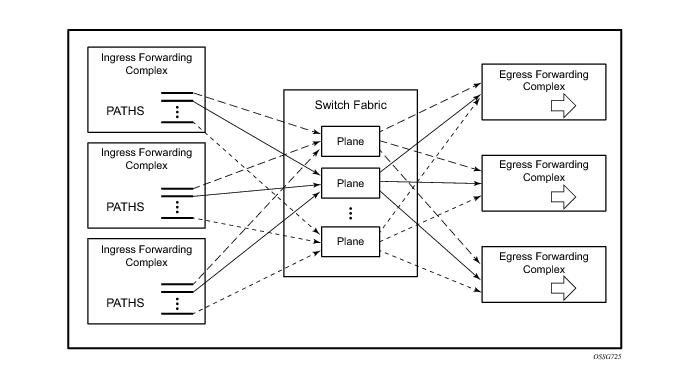
IMPM monitors the ingress rate of IP multicast channels (S,G
1 multicast streams) on line card paths and optimizes the use of the capacity of each switch fabric plane. Its goal is to forward as many channels as possible through the system in order to make maximum use of the switch fabric planes without incurring multicast packet loss. IMPM achieves this by moving entire multicast channels between the line card paths, and therefore between switch fabric planes, to achieve an optimal packing of channels onto path/planes. These actions take into consideration the total ingress multicast traffic being received by all line cards with IMPM enabled and a configured preference of each channel.
A:PE-1# show card
===============================================================================
Card Summary
===============================================================================
Slot Provisioned Equipped Admin Operational Comments
Card-type Card-type State State
-------------------------------------------------------------------------------
6 iom3-xp iom3-xp up up
7 imm8-10gb-xfp imm8-10gb-xfp up up
8 iom3-xp iom3-xp up up
A sfm4-12 sfm4-12 up up/active
B sfm4-12 sfm4-12 up up/standby
===============================================================================
A:PE-1#
A:PE-1# show system switch-fabric high-bandwidth-multicast
===============================================================================
Switch Fabric
===============================================================================
Cap: Planes:
Slot/Mda Min Max Hbm Grp Hi | Lo
-------------------------------------------------------------------------------
6/1 100% 100% No 0 1 0 3 4 5 6 7 8 9 10 11 12 13 14 15 | 16
7/1 100% 100% No 0 19 17 20 21 22 23 24 25 26 27 28 29 30 31 32 | 33
8/1 100% 100% No 0 35 34 36 37 38 39 40 41 42 43 44 45 46 47 0 | 1
A 100% 100% No 0 2 | 2
B 100% 100% No 0 2 | 2
===============================================================================
A:PE-1#
This system has two SF/CPM4s and is using chassis mode d, this creates 24 planes per SF/CPM4 to give a total of 48 planes which are numbered 0-47. The IOM3-XP/IMMs have 16 paths each which are connected to different planes. The SF/CPM4s together use a single plane and an additional plane (18, which is not in the output above) is used by the system itself. As there are more paths (3x16=48) in this configuration than available planes (48-2[system planes 2,18]=46), some planes are shared by multiple paths, namely planes 0 and 1. Note that the path to plane mapping can change after a reboot or after changing hardware.
A:PE-1# show card
===============================================================================
Card Summary
===============================================================================
Slot Provisioned Equipped Admin Operational Comments
Card-type Card-type State State
-------------------------------------------------------------------------------
5 iom2-20g iom2-20g up up
6 iom3-xp iom3-xp up up
7 imm8-10gb-xfp imm8-10gb-xfp up up
8 iom3-xp iom3-xp up up
A sfm4-12 sfm4-12 up up/active
B sfm4-12 sfm4-12 up up/standby
===============================================================================
A:PE-1#
A:PE-1# show system switch-fabric high-bandwidth-multicast
===============================================================================
Switch Fabric
===============================================================================
Cap: Planes:
Slot/Mda Min Max Hbm Grp Hi | Lo
-------------------------------------------------------------------------------
5/1 100% 100% No 0 1 | 0
5/2 100% 100% No 0 4 | 3
6/1 100% 100% No 0 6 5 7 8 9 10 11 12 13 14 15 0 1 3 4 | 5
7/1 100% 100% No 0 7 6 8 9 10 11 12 13 14 15 0 1 3 4 5 | 6
8/1 100% 100% No 0 8 7 9 10 11 12 13 14 15 0 1 3 4 5 6 | 7
A 100% 100% No 0 2 | 2
B 100% 100% No 0 2 | 2
===============================================================================
A:PE-1#
Now that the system is not in chassis mode d, in fact it is in mode a (but the output would be the same in modes
b or
c) the SF/CPM4s each create 8 planes giving a total of 16, numbered 0-15. One plane (2) is used by the SF/CPM4s, leaving 15 (0-1,3-15) planes for connectivity to the line card paths. Each IOM2 forwarding complex has 2 paths, so the paths of the IOM2 in slot 5 are using planes 0 and 1, and 3 and 4. Note that there are now fewer planes available and more paths, so there is more sharing of planes between paths than when chassis mode
d was used.
configure
router
interface "int-IOM3-1"
address 172.16.6.254/24
port 6/2/1
exit
igmp
interface "int-IOM3-1"
static
group 239.255.0.1
starg
exit
exit
exit
no shutdown
exit
pim
interface "int-IOM3-1"
exit
rp
static
address 192.0.2.1
group-prefix 239.255.0.0/16
exit
exit
exit
no shutdown
exit
exit
configure
router
interface "int-IMM8"
address 172.16.3.254/24
port 7/2/1
exit
interface "int-IOM2"
address 172.16.1.254/24
port 5/2/1
exit
interface "int-IOM3-1"
address 172.16.2.254/24
port 6/2/1
exit
interface "int-IOM3-2"
address 172.16.4.254/24
port 8/2/1
exit
exit
|
a.
|
The bandwidth-policy for characteristics relating to the IOM/IMM paths. This is applied on an IOM3-XP/IMM fp 2, or an IOM1/2 MDA, under ingress mcast-path-management, with a bandwidth-policy named default being applied by default. |
config# card slot-number fp 1 ingress mcast-path-management no shutdown
*A:PE-1# tools dump mcast-path-mgr cpm
McPathMgr[6][0]: 0xf33b0a00
PATH: PLANE:
Type SGs InUseBW AvailBW TotalBw ID SGs InUseBW AvailBW TotalBw
P 1 0 - - 1 1 0 2000000 2000000
P 1 0 - - 0 1 0 2000000 2000000
P 1 0 - - 3 1 0 2000000 2000000
P 1 0 - - 4 1 0 2000000 2000000
P 1 0 - - 5 1 0 2000000 2000000
P 1 0 - - 6 1 0 2000000 2000000
P 1 0 - - 7 1 0 2000000 2000000
P 1 0 - - 8 1 0 2000000 2000000
P 1 0 - - 9 1 0 2000000 2000000
P 1 0 - - 10 1 0 2000000 2000000
P 1 0 - - 11 1 0 2000000 2000000
P 1 0 - - 12 1 0 2000000 2000000
P 1 0 - - 13 1 0 2000000 2000000
P 1 0 - - 14 1 0 2000000 2000000
P 1 0 - - 15 1 0 2000000 2000000
S 1 0 - - 16 1 0 1800000 1800000
B 0 0 - - - - - - -
*A:PE-1#
config# mcast-management bandwidth-policy policy-name [create]
mcast-pool percent-of-total percent-of-buffers
resv-cbs percent-of-pool
slope-policy policy-name
config# mcast-management bandwidth-policy policy-name create
t2-paths
primary-path
queue-parameters
cbs percentage
hi-priority-only percent-of-mbs
mbs percentage
secondary-path
number-paths number-of-paths [dual-sfm number-of-paths]
queue-parameters
cbs percentage
hi-priority-only percent-of-mbs
mbs percentage
config# mcast-management multicast-info-policy policy-name [create]
bundle bundle-name [create]
cong-priority-threshold preference-level
config# mcast-management chassis-level
per-mcast-plane-limit megabits-per-second [secondary megabits-per-second]
[dual-sfm megabits-per-second [secondary-dual-sfm megabits-per-second]]
config# card slot-number fp [1]
hi-bw-mcast-src [alarm] [group group-id] [default-paths-only]
config>service>vpls# [spoke-sdp|mesh-sdp] sdp-id:vc-id egress
mfib-allowed-mda-destinations
[no] mda mda-id
config# mcast-management multicast-info-policy policy-name [create]
bundle bundle-name [create]
explicit-sf-path {primary|secondary|ancillary}
config# mcast-management chassis-level
round-robin-inactive-records
config# mcast-management multicast-info-policy policy-name [create]
bundle bundle-name [create]
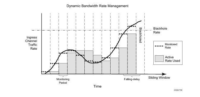
bw-activity {use-admin-bw|dynamic [falling-delay seconds]}
[black-hole-rate kbps]
The above logic is shown in Figure 372 (for simplicity, the falling-delay is exactly twice the monitoring period). It can be seen that the active rate used when the traffic rate decreases follows the highest monitored rate in any falling-delay period.
config# mcast-management bandwidth-policy policy-name create
falling-percent-reset percent-of-highest
config# mcast-management multicast-info-policy policy-name [create]
bundle bundle-name [create]
admin-bw kbps
config# mcast-management bandwidth-policy policy-name create
admin-bw-threshold kilo-bits-per-second
config# mcast-management multicast-info-policy policy-name [create]
bundle bundle-name [create]
preference preference-level
config# card slot-number mda mda-slot ingress mcast-path-management no shutdown
A:PE-1# tools dump mcast-path-mgr cpm
McPathMgr[5][0]: 0xf33b0a00
PATH: PLANE:
Type SGs InUseBW AvailBW TotalBw ID SGs InUseBW AvailBW TotalBw
P 1 0 2000000 2000000 1 1 0 2000000 2000000
S 1 0 1500000 1500000 0 1 0 1800000 1800000
A 0 0 5000000 5000000 - - - - -
B 0 0 - - - - - - -
McPathMgr[5][1]: 0xf33b3198
PATH: PLANE:
Type SGs InUseBW AvailBW TotalBw ID SGs InUseBW AvailBW TotalBw
P 1 0 2000000 2000000 4 1 0 2000000 2000000
S 1 0 1500000 1500000 3 1 0 1800000 1800000
A 0 0 5000000 5000000 - - - - -
B 0 0 - - - - - - -
A:PE-1#
config# mcast-management bandwidth-policy policy-name create
primary-path
queue-parameters
cbs percentage
hi-priority-only percent-of-mbs
mbs percentage
secondary-path
queue-parameters
cbs percentage
hi-priority-only percent-of-mbs
mbs percentage
config# mcast-management bandwidth-policy policy-name create
primary-path
path-limit megabits-per-second
secondary-path
path-limit megabits-per-second
config# card slot-number mda mda-slot
ingress
mcast-path-management
primary-override
path-limit megabits-per-second
secondary-override
path-limit megabits-per-second
config# mcast-management bandwidth-policy policy-name create
ancillary-path
queue-parameters
cbs percentage
hi-priority-only percent-of-mbs
mbs percentage
config# mcast-management bandwidth-policy policy-name create
ancillary-path
path-limit megabits-per-second
config# card slot-number mda mda-slot
ingress
mcast-path-management
ancillary-override
path-limit megabits-per-second
A:PE-1# show card
===============================================================================
Card Summary
===============================================================================
Slot Provisioned Equipped Admin Operational Comments
Card-type Card-type State State
-------------------------------------------------------------------------------
6 iom3-xp iom3-xp up up
7 imm8-10gb-xfp imm8-10gb-xfp up up
8 iom3-xp iom3-xp up up
A sfm4-12 sfm4-12 up up/active
B sfm4-12 sfm4-12 up up/standby
===============================================================================
A:PE-1#
*A:PE-1# show card 6 detail
===============================================================================
Card 6
===============================================================================
Slot Provisioned Equipped Admin Operational Comments
Card-type Card-type State State
-------------------------------------------------------------------------------
6 iom3-xp iom3-xp up up
FP 1 Specific Data
hi-bw-mc-srcEgress Alarm : 2
hi-bw-mc-srcEgress Group : 0
mc-path-mgmt Admin State : In Service
Ingress Bandwidth Policy : default
*A:PE-1# show pools 6/1
===============================================================================
===============================================================================
Type Id App. Pool Name Actual ResvCBS PoolSize
Admin ResvCBS
-------------------------------------------------------------------------------
MDA 6/1 Acc-Ing MC Path Mgmt 18816 37632
50%
===============================================================================
*A:PE-1#
*A:PE-1# show mcast-management bandwidth-policy "default" detail
===============================================================================
Bandwidth Policy Details
===============================================================================
-------------------------------------------------------------------------------
Policy : default
-------------------------------------------------------------------------------
Admin BW Thd : 10 kbps Falling Percent RST: 50
Mcast Pool Total : 10 Mcast Pool Resv Cbs: 50
Slope Policy : default
Primary
Limit : 2000 mbps Cbs : 5.00
Mbs : 7.00 High Priority : 10
Secondary
Limit : 1500 mbps Cbs : 30.00
Mbs : 40.00 High Priority : 10
Ancillary
Limit : 5000 mbps Cbs : 65.00
Mbs : 80.00 High Priority : 10
T2-Primary
Cbs : 5.00 Mbs : 7.00
High Priority : 10
T2-Secondary
Cbs : 30.00 Mbs : 40.00
High Priority : 10 Paths(Single/Dual) : 1/1
===============================================================================
Bandwidth Policies : 1
===============================================================================
*A:PE-1#
*A:PE-1# configure mcast-management
*A:PE-1>config>mcast-mgmt# info detail
----------------------------------------------
multicast-info-policy "default" create
no description
bundle "default" create
no cong-priority-threshold
no description
no ecmp-opt-threshold
no admin-bw
no preference
no keepalive-override
no explicit-sf-path
bw-activity dynamic falling-delay 30
no primary-tunnel-interface
exit
exit
*A:PE-1# tools dump mcast-path-mgr cpm
McPathMgr[6][0]: 0xf33b0a00
PATH: PLANE:
Type SGs InUseBW AvailBW TotalBw ID SGs InUseBW AvailBW TotalBw
P 1 0 - - 4 1 0 2000000 2000000
P 1 0 - - 3 1 0 2000000 2000000
P 1 0 - - 5 1 0 2000000 2000000
P 1 0 - - 6 1 0 2000000 2000000
P 1 0 - - 7 1 0 2000000 2000000
P 1 0 - - 8 1 0 2000000 2000000
P 1 0 - - 9 1 0 2000000 2000000
P 1 0 - - 10 1 0 2000000 2000000
P 1 0 - - 11 1 0 2000000 2000000
P 1 0 - - 12 1 0 2000000 2000000
P 1 0 - - 13 1 0 2000000 2000000
P 1 0 - - 14 1 0 2000000 2000000
P 1 0 - - 15 1 0 2000000 2000000
P 1 0 - - 16 1 0 2000000 2000000
P 1 0 - - 0 1 0 2000000 2000000
S 1 0 - - 1 1 0 1800000 1800000
B 0 0 - - - - - - -
*A:PE-1#
*A:PE-1# show mcast-management chassis
===============================================================================
Chassis Information
===============================================================================
BW per MC plane Single SFM Dual SFM
-------------------------------------------------------------------------------
Primary Path 2000 2000
Secondary Path 1800 1800
-------------------------------------------------------------------------------
MMRP Admin Mode Disabled
MMRP Oper Mode Disabled
Round Robin Inactive Records Disabled
===============================================================================
*A:PE-1#
*A:PE-1# show router pim group detail
===============================================================================
PIM Source Group ipv4
===============================================================================
Group Address : 239.255.0.2
Source Address : 172.16.2.1
RP Address : 192.0.2.1
Flags : spt, rpt-prn-des Type : (S,G)
MRIB Next Hop : 172.16.2.1
MRIB Src Flags : direct Keepalive Timer Exp: 0d 00:03:14
Up Time : 0d 00:00:16 Resolved By : rtable-u
Up JP State : Joined Up JP Expiry : 0d 00:00:00
Up JP Rpt : Pruned Up JP Rpt Override : 0d 00:00:00
Register State : Pruned Register Stop Exp : 0d 00:00:59
Reg From Anycast RP: No
Rpf Neighbor : 172.16.2.1
Incoming Intf : int-IOM3-1
Outgoing Intf List : int-IMM8, int-IOM3-1, int-IOM3-2
Curr Fwding Rate : 9873.0 kbps
Forwarded Packets : 18017 Discarded Packets : 0
Forwarded Octets : 24899494 RPF Mismatches : 0
Spt threshold : 0 kbps ECMP opt threshold : 7
Admin bandwidth : 1 kbps
===============================================================================
*A:PE-1# tools dump mcast-path-mgr cpm
McPathMgr[6][0]: 0xf33b0a00
PATH: PLANE:
Type SGs InUseBW AvailBW TotalBw ID SGs InUseBW AvailBW TotalBw
P 2 9895 - - 4 2 9895 1990105 2000000
P 1 0 - - 3 1 0 2000000 2000000
P 1 0 - - 5 1 0 2000000 2000000
P 1 0 - - 6 1 0 2000000 2000000
P 1 0 - - 7 1 0 2000000 2000000
P 1 0 - - 8 1 0 2000000 2000000
P 1 0 - - 9 1 0 2000000 2000000
P 1 0 - - 10 1 0 2000000 2000000
P 1 0 - - 11 1 0 2000000 2000000
P 1 0 - - 12 1 0 2000000 2000000
P 1 0 - - 13 1 0 2000000 2000000
P 1 0 - - 14 1 0 2000000 2000000
P 1 0 - - 15 1 0 2000000 2000000
P 1 0 - - 16 1 0 2000000 2000000
P 1 0 - - 0 1 0 2000000 2000000
S 1 0 - - 1 1 0 1800000 1800000
B 0 0 - - - - - - -
*A:PE-1#
*A:PE-1# show system switch-fabric high-bandwidth-multicast
===============================================================================
Switch Fabric
===============================================================================
Cap: Planes:
Slot/Mda Min Max Hbm Grp Hi | Lo
-------------------------------------------------------------------------------
6/1 100% 100% No 0 4 3 5 6 7 8 9 10 11 12 13 14 15 16 0 | 1
7/1 100% 100% No 0 19 17 20 21 22 23 24 25 26 27 28 29 30 31 32 | 33
8/1 100% 100% No 0 35 34 36 37 38 39 40 41 42 43 44 45 46 47 0 | 1
A 100% 100% No 0 2 | 2
B 100% 100% No 0 2 | 2
===============================================================================
*A:PE-1#
*A:PE-1# show mcast-management
channel [router router-instance|vpls service-id|service-name service-name]
[mda slot[/mda]]
[group ip-address [source ip-address]]
[path path-type]
[detail]
*A:PE-1# show mcast-management channel
===============================================================================
Multicast Channels
===============================================================================
Legend : D - Dynamic E - Explicit
===============================================================================
Source Address Slot/Cpx Current-Bw Path D/E
Group Address Highest-Bw Plane
-------------------------------------------------------------------------------
172.16.2.1 6/1 9873 Primary D
239.255.0.2 9873 4
===============================================================================
Multicast Channels : 1
===============================================================================
*A:PE-1#
*A:PE-1# show mcast-management channel detail
===============================================================================
Multicast Channels
===============================================================================
-------------------------------------------------------------------------------
Source Address : 172.16.2.1
Group Address : 239.255.0.2
-------------------------------------------------------------------------------
Slot/Complex : 6/1 Current Bw : 9873 kbps
Dynamic/Explicit : Dynamic Current Path : Primary
Oper Admin Bw : 0 kbps Current Plane : 4
Ing last highest : 9873 Preference : 0
Black-hole rate : None Ing sec highest : 9873
Time remaining : 30 seconds Blackhole : No
===============================================================================
Multicast Channels : 1
===============================================================================
*A:PE-1#
*A:PE-1# tools dump mcast-path-mgr channels slot 6
===============================================================================
Slot: 6 Complex: 0
===============================================================================
Source address CurrBw Plane PathType Path Pref
Group address PathBw Repl Exp BlkHoleBw
-------------------------------------------------------------------------------
172.16.2.1 9873 4 primary 0 0
239.255.0.2 9873 2 none 0
Unmanaged traffic 0 4 primary 0 8
slot: 6 cmplx: 0 path: 0 0 0 none 0
Unmanaged traffic 0 3 primary 1 8
slot: 6 cmplx: 0 path: 1 0 0 none 0
Unmanaged traffic 0 5 primary 2 8
slot: 6 cmplx: 0 path: 2 0 0 none 0
Unmanaged traffic 0 6 primary 3 8
slot: 6 cmplx: 0 path: 3 0 0 none 0
Unmanaged traffic 0 7 primary 4 8
slot: 6 cmplx: 0 path: 4 0 0 none 0
Unmanaged traffic 0 8 primary 5 8
slot: 6 cmplx: 0 path: 5 0 0 none 0
Unmanaged traffic 0 9 primary 6 8
slot: 6 cmplx: 0 path: 6 0 0 none 0
Unmanaged traffic 0 10 primary 7 8
slot: 6 cmplx: 0 path: 7 0 0 none 0
Unmanaged traffic 0 11 primary 8 8
slot: 6 cmplx: 0 path: 8 0 0 none 0
Unmanaged traffic 0 12 primary 9 8
slot: 6 cmplx: 0 path: 9 0 0 none 0
Unmanaged traffic 0 13 primary 10 8
slot: 6 cmplx: 0 path: 10 0 0 none 0
Unmanaged traffic 0 14 primary 11 8
slot: 6 cmplx: 0 path: 11 0 0 none 0
Unmanaged traffic 0 15 primary 12 8
slot: 6 cmplx: 0 path: 12 0 0 none 0
Unmanaged traffic 0 16 primary 13 8
slot: 6 cmplx: 0 path: 13 0 0 none 0
Unmanaged traffic 0 0 primary 14 8
slot: 6 cmplx: 0 path: 14 0 0 none 0
Unmanaged traffic 0 1 secondary 15 8
slot: 6 cmplx: 0 path: 15 0 0 none 0
*A:PE-1#
*A:PE-1# configure mcast-management
*A:PE-1>config>mcast-mgmt# info
----------------------------------------------
bandwidth-policy "bandwidth-policy-1" create
admin-bw-threshold 8000
exit
multicast-info-policy "multicast-info-policy-1" create
bundle "default" create
exit
bundle "bundle-1" create
channel "239.255.0.1" "239.255.0.16" create
admin-bw 12000
bw-activity use-admin-bw black-hole-rate 15000
exit
exit
exit
----------------------------------------------
*A:PE-1>config>mcast-mgmt# exit all
*A:PE-1# show mcast-management channel group 239.255.0.2 detail
===============================================================================
Multicast Channels
===============================================================================
-------------------------------------------------------------------------------
Source Address : 172.16.2.1
Group Address : 239.255.0.2
-------------------------------------------------------------------------------
Slot/Complex : 6/1 Current Bw : 9873 kbps
Dynamic/Explicit : Dynamic Current Path : Primary
Oper Admin Bw : 12000 kbps Current Plane : 4
Ing last highest : 12000 Preference : 0
Black-hole rate : 15000 kbps Ing sec highest : 12000
Time remaining : 30 seconds Blackhole : No
===============================================================================
Multicast Channels : 1
===============================================================================
*A:PE-1#
*A:PE-1# tools dump mcast-path-mgr cpm
McPathMgr[6][0]: 0xf33b0a00
PATH: PLANE:
Type SGs InUseBW AvailBW TotalBw ID SGs InUseBW AvailBW TotalBw
P 2 12000 - - 4 2 12000 1988000 2000000
P 1 0 - - 3 1 0 2000000 2000000
P 1 0 - - 5 1 0 2000000 2000000
P 1 0 - - 6 1 0 2000000 2000000
P 1 0 - - 7 1 0 2000000 2000000
P 1 0 - - 8 1 0 2000000 2000000
P 1 0 - - 9 1 0 2000000 2000000
P 1 0 - - 10 1 0 2000000 2000000
P 1 0 - - 11 1 0 2000000 2000000
P 1 0 - - 12 1 0 2000000 2000000
P 1 0 - - 13 1 0 2000000 2000000
P 1 0 - - 14 1 0 2000000 2000000
P 1 0 - - 15 1 0 2000000 2000000
P 1 0 - - 16 1 0 2000000 2000000
P 1 0 - - 0 1 0 2000000 2000000
S 1 0 - - 1 1 0 1800000 1800000
B 0 0 - - - - - - -
*A:PE-1#
*A:PE-1#
11 2011/10/21 01:40:13.21 UTC MINOR: MCPATH #2001 Base Black-hole-rate is reached
"Channel (172.16.2.1,239.255.0.2) for vRtr instance 1 slot/cplx 6/1 has been blackholed."
*A:PE-1# show mcast-management channel group 239.255.0.2 detail
===============================================================================
Multicast Channels
===============================================================================
-------------------------------------------------------------------------------
Source Address : 172.16.2.1
Group Address : 239.255.0.2
-------------------------------------------------------------------------------
Slot/Complex : 6/1 Current Bw : 19458 kbps
Dynamic/Explicit : Dynamic Current Path : Blackhole
Oper Admin Bw : 12000 kbps Current Plane : N/A
Ing last highest : 19480 Preference : 0
Black-hole rate : 15000 kbps Ing sec highest : 19469
Time remaining : 23 seconds Blackhole : Yes
===============================================================================
Multicast Channels : 1
===============================================================================
*A:PE-1#
*A:PE-1# tools dump mcast-path-mgr cpm
McPathMgr[6][0]: 0xf33b0a00
PATH: PLANE:
Type SGs InUseBW AvailBW TotalBw ID SGs InUseBW AvailBW TotalBw
P 1 0 - - 4 1 0 2000000 2000000
P 1 0 - - 3 1 0 2000000 2000000
P 1 0 - - 5 1 0 2000000 2000000
P 1 0 - - 6 1 0 2000000 2000000
P 1 0 - - 7 1 0 2000000 2000000
P 1 0 - - 8 1 0 2000000 2000000
P 1 0 - - 9 1 0 2000000 2000000
P 1 0 - - 10 1 0 2000000 2000000
P 1 0 - - 11 1 0 2000000 2000000
P 1 0 - - 12 1 0 2000000 2000000
P 1 0 - - 13 1 0 2000000 2000000
P 1 0 - - 14 1 0 2000000 2000000
P 1 0 - - 15 1 0 2000000 2000000
P 1 0 - - 16 1 0 2000000 2000000
P 1 0 - - 0 1 0 2000000 2000000
S 1 0 - - 1 1 0 1800000 1800000
B 1 19480 - - - - - - -
*A:PE-1#
7 2011/10/22 21:53:43.54 UTC MINOR: MCPATH #2001 Base No bandwidth available
"Channel (172.16.2.1,239.255.0.2) for vRtr instance 1 slot/cplx 6/1 has been blackholed."
6 2011/10/21 00:27:58.00 UTC MINOR: MCPATH #2002 Base
"Channel (0.0.0.0,0.6.0.0) for unknown value (2) instance 0 slot/cplx 6/1 is no longer being blackholed."
*A:PE-1# configure card 6 fp hi-bw-mcast-src group 1 alarm
*A:PE-1# show system switch-fabric high-bandwidth-multicast
===============================================================================
Switch Fabric
===============================================================================
Cap: Planes:
Slot/Mda Min Max Hbm Grp Hi | Lo
-------------------------------------------------------------------------------
6/1 100% 100% Yes 1 4 3 5 6 7 8 9 10 11 12 13 14 15 16 0 | 1
7/1 100% 100% No 0 19 17 20 21 22 23 24 25 26 27 28 29 30 31 32 | 33
8/1 100% 100% No 0 35 34 36 37 38 39 40 41 42 43 44 45 46 47 0 | 1
A 100% 100% No 0 2 | 2
B 100% 100% No 0 2 | 2
===============================================================================
*A:PE-1#
*A:PE-1# configure card 8 fp hi-bw-mcast-src group 2 alarm
*A:PE-1# show system switch-fabric high-bandwidth-multicast
===============================================================================
Switch Fabric
===============================================================================
Cap: Planes:
Slot/Mda Min Max Hbm Grp Hi | Lo
-------------------------------------------------------------------------------
6/1 100% 100% Yes 1 4 3 5 6 7 8 9 10 11 12 13 14 15 16 0 | 1
7/1 100% 100% No 0 19 17 20 21 22 23 24 25 26 27 28 29 30 31 32 | 33
8/1 100% 100% Yes 2 35 34 36 37 38 39 40 41 42 43 44 45 46 47 17 | 19
A 100% 100% No 0 2 | 2
B 100% 100% No 0 2 | 2
===============================================================================
*A:PE-1#
*A:PE-1# configure card 7 fp hi-bw-mcast-src group 3 alarm
*A:PE-1#
7 2011/10/21 00:35:50.95 UTC MINOR: CHASSIS #2052 Base Mda 6/1
"Class MDA Module : Plane shared by multiple multicast high bandwidth taps"
8 2011/10/21 00:35:50.95 UTC MINOR: CHASSIS #2052 Base Mda 6/2
"Class MDA Module : Plane shared by multiple multicast high bandwidth taps"
9 2011/10/21 00:35:50.97 UTC MINOR: CHASSIS #2052 Base Mda 7/1
"Class MDA Module : Plane shared by multiple multicast high bandwidth taps"
10 2011/10/21 00:35:50.97 UTC MINOR: CHASSIS #2052 Base Mda 7/2
"Class MDA Module : Plane shared by multiple multicast high bandwidth taps"
*A:PE-1# show system switch-fabric high-bandwidth-multicast
===============================================================================
Switch Fabric
===============================================================================
Cap: Planes:
Slot/Mda Min Max Hbm Grp Hi | Lo
-------------------------------------------------------------------------------
6/1 100% 100% Yes 1 4 3 5 6 7 8 9 10 11 12 13 14 15 16 0 | 1
7/1 100% 100% Yes 3 21 20 22 23 24 25 26 27 28 29 30 31 32 33 0 | 1
8/1 100% 100% Yes 2 35 34 36 37 38 39 40 41 42 43 44 45 46 47 17 | 19
A 100% 100% No 0 2 | 2
B 100% 100% No 0 2 | 2
===============================================================================
*A:PE-1#
A common example of the use of the hi-bw-mcast-src command would be when cards 6 and 8 have uplink ports on which high bandwidth multicast channels could be received. It would be desired to have these cards use different planes. To achieve this, card 7 could be configured into group 1, as follows.
*A:PE-1# configure card 7 fp hi-bw-mcast-src group 1 alarm
*A:PE-1# show system switch-fabric high-bandwidth-multicast
===============================================================================
Switch Fabric
===============================================================================
Cap: Planes:
Slot/Mda Min Max Hbm Grp Hi | Lo
-------------------------------------------------------------------------------
6/1 100% 100% Yes 1 4 3 5 6 7 8 9 10 11 12 13 14 15 16 0 | 1
7/1 100% 100% Yes 1 4 3 5 6 7 8 9 10 11 12 13 14 15 16 0 | 1
8/1 100% 100% Yes 2 35 34 36 37 38 39 40 41 42 43 44 45 46 47 17 | 19
A 100% 100% No 0 2 | 2
B 100% 100% No 0 2 | 2
===============================================================================
*A:PE-1#
*A:PE-1# tools dump mcast-path-mgr cpm
McPathMgr[6][0]: 0xf33b0a00
PATH: PLANE:
Type SGs InUseBW AvailBW TotalBw ID SGs InUseBW AvailBW TotalBw
P 2 9707 - - 4 3 9707 1990293 2000000
P 1 0 - - 3 2 0 2000000 2000000
...
McPathMgr[7][0]: 0xf33b3198
PATH: PLANE:
Type SGs InUseBW AvailBW TotalBw ID SGs InUseBW AvailBW TotalBw
P 1 0 - - 4 3 9707 1990293 2000000
P 1 0 - - 3 2 0 2000000 2000000
*A:PE-1# show service id 2 sap 7/2/1:3 stats
===============================================================================
Service Access Points(SAP)
===============================================================================
-------------------------------------------------------------------------------
Sap per Queue stats
-------------------------------------------------------------------------------
Packets Octets
Ingress Queue 1 (Unicast) (Priority)
Off. HiPrio : 0 0
Off. LoPrio : 0 0
Dro. HiPrio : 0 0
Dro. LoPrio : 0 0
For. InProf : 0 0
For. OutProf : 0 0
Ingress Queue 11 (Multipoint) (Priority)
Off. HiPrio : 0 0
Off. LoPrio : 0 0
Off. Managed : 149410 209771640
Dro. HiPrio : 0 0
Dro. LoPrio : 0 0
For. InProf : 149410 209771640
For. OutProf : 0 0
Egress Queue 1
For. InProf : 0 0
For. OutProf : 0 0
Dro. InProf : 0 0
Dro. OutProf : 0 0
===============================================================================
*A:PE-1#
A:PE-1# show card
===============================================================================
Card Summary
===============================================================================
Slot Provisioned Equipped Admin Operational Comments
Card-type Card-type State State
-------------------------------------------------------------------------------
5 iom2-20g iom2-20g up up
6 iom3-xp iom3-xp up up
7 imm8-10gb-xfp imm8-10gb-xfp up up
8 iom3-xp iom3-xp up up
A sfm4-12 sfm4-12 up up/active
B sfm4-12 sfm4-12 up up/standby
===============================================================================
A:PE-1#
A:PE-1# show mcast-management mda
===============================================================================
MDA Summary
===============================================================================
S/C Policy Type In-use-Bw Admin
-------------------------------------------------------------------------------
5/1 default Primary 0 Kbps up
default Secondary 0 Kbps up
default Ancillary 0 Kbps up
5/2 default Primary 0 Kbps up
default Secondary 0 Kbps up
default Ancillary 0 Kbps up
6/2 default Primary 0 Kbps down
default Secondary 0 Kbps down
default Ancillary 0 Kbps down
7/1 default Primary 0 Kbps down
default Secondary 0 Kbps down
default Ancillary 0 Kbps down
7/2 default Primary 0 Kbps down
default Secondary 0 Kbps down
default Ancillary 0 Kbps down
8/2 default Primary 0 Kbps down
default Secondary 0 Kbps down
default Ancillary 0 Kbps down
===============================================================================
A:PE-1#
*A:PE-1# show system switch-fabric high-bandwidth-multicast
===============================================================================
Switch Fabric
===============================================================================
Cap: Planes:
Slot/Mda Min Max Hbm Grp Hi | Lo
-------------------------------------------------------------------------------
5/1 100% 100% No 0 1 | 0
5/2 100% 100% No 0 4 | 3
6/1 100% 100% No 0 6 5 7 8 9 10 11 12 13 14 15 0 1 3 4 | 5
7/1 100% 100% No 0 7 6 8 9 10 11 12 13 14 15 0 1 3 4 5 | 6
8/1 100% 100% No 0 8 7 9 10 11 12 13 14 15 0 1 3 4 5 6 | 7
A 100% 100% No 0 2 | 2
B 100% 100% No 0 2 | 2
===============================================================================
*A:PE-1#
*A:PE-1# tools dump mcast-path-mgr cpm
McPathMgr[5][0]: 0xf33b0a00
PATH: PLANE:
Type SGs InUseBW AvailBW TotalBw ID SGs InUseBW AvailBW TotalBw
P 1 0 2000000 2000000 1 1 0 2000000 2000000
S 1 0 1500000 1500000 0 1 0 1800000 1800000
A 0 0 5000000 5000000 - - - - -
B 0 0 - - - - - - -
McPathMgr[5][1]: 0xf33b3198
PATH: PLANE:
Type SGs InUseBW AvailBW TotalBw ID SGs InUseBW AvailBW TotalBw
P 1 0 2000000 2000000 4 1 0 2000000 2000000
S 1 0 1500000 1500000 3 1 0 1800000 1800000
A 0 0 5000000 5000000 - - - - -
B 0 0 - - - - - - -
*A:PE-1#
*A:PE-1# show router pim group 239.255.0.1 detail
===============================================================================
PIM Source Group ipv4
===============================================================================
Group Address : 239.255.0.1
Source Address : 172.16.1.1
RP Address : 192.0.2.1
Flags : spt, rpt-prn-des Type : (S,G)
MRIB Next Hop : 172.16.1.1
MRIB Src Flags : direct Keepalive Timer Exp: 0d 00:02:44
Up Time : 0d 00:07:45 Resolved By : rtable-u
Up JP State : Joined Up JP Expiry : 0d 00:00:00
Up JP Rpt : Pruned Up JP Rpt Override : 0d 00:00:00
Register State : Pruned Register Stop Exp : 0d 00:00:32
Reg From Anycast RP: No
Rpf Neighbor : 172.16.1.1
Incoming Intf : int-IOM2
Outgoing Intf List : int-IMM8, int-IOM3-1, int-IOM3-2
Curr Fwding Rate : 9734.8 kbps
Forwarded Packets : 591874 Discarded Packets : 0
Forwarded Octets : 817969868 RPF Mismatches : 0
Spt threshold : 0 kbps ECMP opt threshold : 7
Admin bandwidth : 1 kbps
-------------------------------------------------------------------------------
*A:PE-1# show mcast-management channel
===============================================================================
Multicast Channels
===============================================================================
Legend : D - Dynamic E - Explicit
===============================================================================
Source Address Slot/Cpx Current-Bw Path D/E
Group Address Highest-Bw Plane
-------------------------------------------------------------------------------
172.16.1.1 5/2 9729 Ancillary D
239.255.0.1 9740 -
===============================================================================
Multicast Channels : 1
===============================================================================
*A:PE-1#
*A:PE-1# show mcast-management channel detail
===============================================================================
Multicast Channels
===============================================================================
-------------------------------------------------------------------------------
Source Address : 172.16.1.1
Group Address : 239.255.0.1
-------------------------------------------------------------------------------
Slot/Complex : 5/2 Current Bw : 9729 kbps
Dynamic/Explicit : Dynamic Current Path : Ancillary
Oper Admin Bw : 0 kbps Current Plane : N/A
Ing last highest : 9740 Preference : 0
Black-hole rate : None Ing sec highest : 9740
Time remaining : 27 seconds Blackhole : No
===============================================================================
Multicast Channels : 1
===============================================================================
*A:PE-1#
*A:PE-1# tools dump mcast-path-mgr cpm
McPathMgr[5][0]: 0xf33b0a00
PATH: PLANE:
Type SGs InUseBW AvailBW TotalBw ID SGs InUseBW AvailBW TotalBw
P 1 0 2000000 2000000 1 1 0 2000000 2000000
S 1 0 1500000 1500000 0 1 0 1800000 1800000
A 0 0 5000000 5000000 - - - - -
B 0 0 - - - - - - -
McPathMgr[5][1]: 0xf33b3198
PATH: PLANE:
Type SGs InUseBW AvailBW TotalBw ID SGs InUseBW AvailBW TotalBw
P 1 0 2000000 2000000 4 1 0 2000000 2000000
S 1 0 1500000 1500000 3 1 0 1800000 1800000
A 1 19480 4980520 5000000 - - - - -
B 0 0 - - - - - - -
*A:PE-1#
*A:PE-1# tools dump mcast-path-mgr channels
===============================================================================
Slot: 5 Complex: 0
===============================================================================
Source address CurrBw Plane PathType Path Pref
Group address PathBw Repl Exp BlkHoleBw
-------------------------------------------------------------------------------
Unmanaged traffic 0 1 primary 0 8
slot: 5 cmplx: 0 path: 0 0 0 none 0
Unmanaged traffic 0 0 secondary 1 8
slot: 5 cmplx: 0 path: 1 0 0 none 0
===============================================================================
Slot: 5 Complex: 1
===============================================================================
Source address CurrBw Plane PathType Path Pref
Group address PathBw Repl Exp BlkHoleBw
-------------------------------------------------------------------------------
172.16.1.1 9740 48 ancillary 16 0
239.255.0.1 19480 2 none 0
Unmanaged traffic 0 4 primary 0 8
slot: 5 cmplx: 1 path: 0 0 0 none 0
Unmanaged traffic 0 3 secondary 1 8
slot: 5 cmplx: 1 path: 1 0 0 none 0
*A:PE-1#


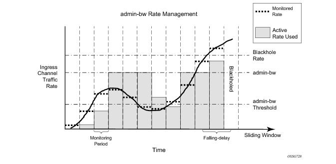
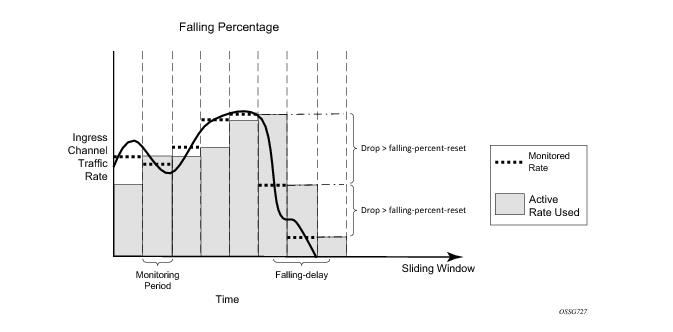 Figure 373: Falling-Percent-Resetconfig# mcast-management multicast-info-policy policy-name [create]bundle bundle-name [create]admin-bw kbpsconfig# mcast-management bandwidth-policy policy-name createadmin-bw-threshold kilo-bits-per-secondIMPM will use the rate configured for the admin-bw if the monitored rate is above the admin-bw-threshold but below or equal to the admin-bw in the sliding window of the falling-delay. Whenever the monitored rate is below the admin-bw-threshold or above the admin-bw, IMPM uses the dynamic rate management mechanism. The admin-bw-threshold needs to be smaller than the admin-bw, with the latter being non-zero. This is shown in Figure 374 (for simplicity, the falling-delay is exactly twice the monitoring period). It can be seen that while the monitored rate stays between the admin-bw-threshold and the admin-bw, the active rate used is set to the admin-bw.Figure 374: Admin-Bw Rate Managementconfig# mcast-management multicast-info-policy policy-name [create]bundle bundle-name [create]preference preference-levelconfig# card slot-number mda mda-slot ingress mcast-path-management no shutdownA:PE-1# tools dump mcast-path-mgr cpmMcPathMgr[5][0]: 0xf33b0a00PATH: PLANE:Type SGs InUseBW AvailBW TotalBw ID SGs InUseBW AvailBW TotalBwP 1 0 2000000 2000000 1 1 0 2000000 2000000S 1 0 1500000 1500000 0 1 0 1800000 1800000A 0 0 5000000 5000000 - - - - -B 0 0 - - - - - - -McPathMgr[5][1]: 0xf33b3198PATH: PLANE:Type SGs InUseBW AvailBW TotalBw ID SGs InUseBW AvailBW TotalBwP 1 0 2000000 2000000 4 1 0 2000000 2000000S 1 0 1500000 1500000 3 1 0 1800000 1800000A 0 0 5000000 5000000 - - - - -B 0 0 - - - - - - -A:PE-1#Output 4: Paths/Planes on IOM1/2config# mcast-management bandwidth-policy policy-name createprimary-pathqueue-parameterscbs percentagehi-priority-only percent-of-mbsmbs percentagesecondary-pathqueue-parameterscbs percentagehi-priority-only percent-of-mbsmbs percentageconfig# mcast-management bandwidth-policy policy-name createprimary-pathpath-limit megabits-per-secondsecondary-pathpath-limit megabits-per-secondconfig# card slot-number mda mda-slotingressmcast-path-managementprimary-overridepath-limit megabits-per-secondsecondary-overridepath-limit megabits-per-secondconfig# mcast-management bandwidth-policy policy-name createancillary-pathqueue-parameterscbs percentagehi-priority-only percent-of-mbsmbs percentageconfig# mcast-management bandwidth-policy policy-name createancillary-pathpath-limit megabits-per-secondconfig# card slot-number mda mda-slotingressmcast-path-managementancillary-overridepath-limit megabits-per-secondThis section includes the show output related to IMPM. The first part covers generic output and uses IOM3-XP/IMMs and chassis mode d. The second part includes an IOM2 and so uses chassis mode a.A:PE-1# show card===============================================================================Card Summary===============================================================================Slot Provisioned Equipped Admin Operational CommentsCard-type Card-type State State-------------------------------------------------------------------------------6 iom3-xp iom3-xp up up7 imm8-10gb-xfp imm8-10gb-xfp up up8 iom3-xp iom3-xp up upA sfm4-12 sfm4-12 up up/activeB sfm4-12 sfm4-12 up up/standby===============================================================================A:PE-1#*A:PE-1# show card 6 detail===============================================================================Card 6===============================================================================Slot Provisioned Equipped Admin Operational CommentsCard-type Card-type State State-------------------------------------------------------------------------------6 iom3-xp iom3-xp up upFP 1 Specific Datahi-bw-mc-srcEgress Alarm : 2hi-bw-mc-srcEgress Group : 0mc-path-mgmt Admin State : In ServiceIngress Bandwidth Policy : default*A:PE-1# show pools 6/1==============================================================================================================================================================Type Id App. Pool Name Actual ResvCBS PoolSizeAdmin ResvCBS-------------------------------------------------------------------------------MDA 6/1 Acc-Ing MC Path Mgmt 18816 3763250%===============================================================================*A:PE-1#*A:PE-1# show mcast-management bandwidth-policy "default" detail===============================================================================Bandwidth Policy Details===============================================================================-------------------------------------------------------------------------------Policy : default-------------------------------------------------------------------------------Admin BW Thd : 10 kbps Falling Percent RST: 50Mcast Pool Total : 10 Mcast Pool Resv Cbs: 50Slope Policy : defaultPrimaryLimit : 2000 mbps Cbs : 5.00Mbs : 7.00 High Priority : 10SecondaryLimit : 1500 mbps Cbs : 30.00Mbs : 40.00 High Priority : 10AncillaryLimit : 5000 mbps Cbs : 65.00Mbs : 80.00 High Priority : 10T2-PrimaryCbs : 5.00 Mbs : 7.00High Priority : 10T2-SecondaryCbs : 30.00 Mbs : 40.00High Priority : 10 Paths(Single/Dual) : 1/1===============================================================================Bandwidth Policies : 1===============================================================================*A:PE-1#*A:PE-1# configure mcast-management*A:PE-1>config>mcast-mgmt# info detail----------------------------------------------multicast-info-policy "default" createno descriptionbundle "default" createno cong-priority-thresholdno descriptionno ecmp-opt-thresholdno admin-bwno preferenceno keepalive-overrideno explicit-sf-pathbw-activity dynamic falling-delay 30no primary-tunnel-interfaceexitexit*A:PE-1# tools dump mcast-path-mgr cpmMcPathMgr[6][0]: 0xf33b0a00PATH: PLANE:Type SGs InUseBW AvailBW TotalBw ID SGs InUseBW AvailBW TotalBwP 1 0 - - 4 1 0 2000000 2000000P 1 0 - - 3 1 0 2000000 2000000P 1 0 - - 5 1 0 2000000 2000000P 1 0 - - 6 1 0 2000000 2000000P 1 0 - - 7 1 0 2000000 2000000P 1 0 - - 8 1 0 2000000 2000000P 1 0 - - 9 1 0 2000000 2000000P 1 0 - - 10 1 0 2000000 2000000P 1 0 - - 11 1 0 2000000 2000000P 1 0 - - 12 1 0 2000000 2000000P 1 0 - - 13 1 0 2000000 2000000P 1 0 - - 14 1 0 2000000 2000000P 1 0 - - 15 1 0 2000000 2000000P 1 0 - - 16 1 0 2000000 2000000P 1 0 - - 0 1 0 2000000 2000000S 1 0 - - 1 1 0 1800000 1800000B 0 0 - - - - - - -*A:PE-1#*A:PE-1# show mcast-management chassis===============================================================================Chassis Information===============================================================================BW per MC plane Single SFM Dual SFM-------------------------------------------------------------------------------Primary Path 2000 2000Secondary Path 1800 1800-------------------------------------------------------------------------------MMRP Admin Mode DisabledMMRP Oper Mode DisabledRound Robin Inactive Records Disabled===============================================================================*A:PE-1#*A:PE-1# show router pim group detail===============================================================================PIM Source Group ipv4===============================================================================Group Address : 239.255.0.2Source Address : 172.16.2.1RP Address : 192.0.2.1Flags : spt, rpt-prn-des Type : (S,G)MRIB Next Hop : 172.16.2.1MRIB Src Flags : direct Keepalive Timer Exp: 0d 00:03:14Up Time : 0d 00:00:16 Resolved By : rtable-uUp JP State : Joined Up JP Expiry : 0d 00:00:00Up JP Rpt : Pruned Up JP Rpt Override : 0d 00:00:00Register State : Pruned Register Stop Exp : 0d 00:00:59Reg From Anycast RP: NoRpf Neighbor : 172.16.2.1Incoming Intf : int-IOM3-1Outgoing Intf List : int-IMM8, int-IOM3-1, int-IOM3-2Curr Fwding Rate : 9873.0 kbpsForwarded Packets : 18017 Discarded Packets : 0Forwarded Octets : 24899494 RPF Mismatches : 0Spt threshold : 0 kbps ECMP opt threshold : 7Admin bandwidth : 1 kbps===============================================================================*A:PE-1# tools dump mcast-path-mgr cpmMcPathMgr[6][0]: 0xf33b0a00PATH: PLANE:Type SGs InUseBW AvailBW TotalBw ID SGs InUseBW AvailBW TotalBwP 2 9895 - - 4 2 9895 1990105 2000000P 1 0 - - 3 1 0 2000000 2000000P 1 0 - - 5 1 0 2000000 2000000P 1 0 - - 6 1 0 2000000 2000000P 1 0 - - 7 1 0 2000000 2000000P 1 0 - - 8 1 0 2000000 2000000P 1 0 - - 9 1 0 2000000 2000000P 1 0 - - 10 1 0 2000000 2000000P 1 0 - - 11 1 0 2000000 2000000P 1 0 - - 12 1 0 2000000 2000000P 1 0 - - 13 1 0 2000000 2000000P 1 0 - - 14 1 0 2000000 2000000P 1 0 - - 15 1 0 2000000 2000000P 1 0 - - 16 1 0 2000000 2000000P 1 0 - - 0 1 0 2000000 2000000S 1 0 - - 1 1 0 1800000 1800000B 0 0 - - - - - - -*A:PE-1#*A:PE-1# show system switch-fabric high-bandwidth-multicast===============================================================================Switch Fabric===============================================================================Cap: Planes:Slot/Mda Min Max Hbm Grp Hi | Lo-------------------------------------------------------------------------------6/1 100% 100% No 0 4 3 5 6 7 8 9 10 11 12 13 14 15 16 0 | 17/1 100% 100% No 0 19 17 20 21 22 23 24 25 26 27 28 29 30 31 32 | 338/1 100% 100% No 0 35 34 36 37 38 39 40 41 42 43 44 45 46 47 0 | 1A 100% 100% No 0 2 | 2B 100% 100% No 0 2 | 2===============================================================================*A:PE-1#*A:PE-1# show mcast-managementchannel [router router-instance|vpls service-id|service-name service-name][mda slot[/mda]][group ip-address [source ip-address]][path path-type][detail]*A:PE-1# show mcast-management channel===============================================================================Multicast Channels===============================================================================Legend : D - Dynamic E - Explicit===============================================================================Source Address Slot/Cpx Current-Bw Path D/EGroup Address Highest-Bw Plane-------------------------------------------------------------------------------172.16.2.1 6/1 9873 Primary D239.255.0.2 9873 4===============================================================================Multicast Channels : 1===============================================================================*A:PE-1#*A:PE-1# show mcast-management channel detail===============================================================================Multicast Channels===============================================================================-------------------------------------------------------------------------------Source Address : 172.16.2.1Group Address : 239.255.0.2-------------------------------------------------------------------------------Slot/Complex : 6/1 Current Bw : 9873 kbpsDynamic/Explicit : Dynamic Current Path : PrimaryOper Admin Bw : 0 kbps Current Plane : 4Ing last highest : 9873 Preference : 0Black-hole rate : None Ing sec highest : 9873Time remaining : 30 seconds Blackhole : No===============================================================================Multicast Channels : 1===============================================================================*A:PE-1#*A:PE-1# tools dump mcast-path-mgr channels slot 6===============================================================================Slot: 6 Complex: 0===============================================================================Source address CurrBw Plane PathType Path PrefGroup address PathBw Repl Exp BlkHoleBw-------------------------------------------------------------------------------172.16.2.1 9873 4 primary 0 0239.255.0.2 9873 2 none 0Unmanaged traffic 0 4 primary 0 8slot: 6 cmplx: 0 path: 0 0 0 none 0Unmanaged traffic 0 3 primary 1 8slot: 6 cmplx: 0 path: 1 0 0 none 0Unmanaged traffic 0 5 primary 2 8slot: 6 cmplx: 0 path: 2 0 0 none 0Unmanaged traffic 0 6 primary 3 8slot: 6 cmplx: 0 path: 3 0 0 none 0Unmanaged traffic 0 7 primary 4 8slot: 6 cmplx: 0 path: 4 0 0 none 0Unmanaged traffic 0 8 primary 5 8slot: 6 cmplx: 0 path: 5 0 0 none 0Unmanaged traffic 0 9 primary 6 8slot: 6 cmplx: 0 path: 6 0 0 none 0Unmanaged traffic 0 10 primary 7 8slot: 6 cmplx: 0 path: 7 0 0 none 0Unmanaged traffic 0 11 primary 8 8slot: 6 cmplx: 0 path: 8 0 0 none 0Unmanaged traffic 0 12 primary 9 8slot: 6 cmplx: 0 path: 9 0 0 none 0Unmanaged traffic 0 13 primary 10 8slot: 6 cmplx: 0 path: 10 0 0 none 0Unmanaged traffic 0 14 primary 11 8slot: 6 cmplx: 0 path: 11 0 0 none 0Unmanaged traffic 0 15 primary 12 8slot: 6 cmplx: 0 path: 12 0 0 none 0Unmanaged traffic 0 16 primary 13 8slot: 6 cmplx: 0 path: 13 0 0 none 0Unmanaged traffic 0 0 primary 14 8slot: 6 cmplx: 0 path: 14 0 0 none 0Unmanaged traffic 0 1 secondary 15 8slot: 6 cmplx: 0 path: 15 0 0 none 0*A:PE-1#*A:PE-1# configure mcast-management*A:PE-1>config>mcast-mgmt# info----------------------------------------------bandwidth-policy "bandwidth-policy-1" createadmin-bw-threshold 8000exitmulticast-info-policy "multicast-info-policy-1" createbundle "default" createexitbundle "bundle-1" createchannel "239.255.0.1" "239.255.0.16" createadmin-bw 12000bw-activity use-admin-bw black-hole-rate 15000exitexitexit----------------------------------------------*A:PE-1>config>mcast-mgmt# exit all*A:PE-1# show mcast-management channel group 239.255.0.2 detail===============================================================================Multicast Channels===============================================================================-------------------------------------------------------------------------------Source Address : 172.16.2.1Group Address : 239.255.0.2-------------------------------------------------------------------------------Slot/Complex : 6/1 Current Bw : 9873 kbpsDynamic/Explicit : Dynamic Current Path : PrimaryOper Admin Bw : 12000 kbps Current Plane : 4Ing last highest : 12000 Preference : 0Black-hole rate : 15000 kbps Ing sec highest : 12000Time remaining : 30 seconds Blackhole : No===============================================================================Multicast Channels : 1===============================================================================*A:PE-1#*A:PE-1# tools dump mcast-path-mgr cpmMcPathMgr[6][0]: 0xf33b0a00PATH: PLANE:Type SGs InUseBW AvailBW TotalBw ID SGs InUseBW AvailBW TotalBwP 2 12000 - - 4 2 12000 1988000 2000000P 1 0 - - 3 1 0 2000000 2000000P 1 0 - - 5 1 0 2000000 2000000P 1 0 - - 6 1 0 2000000 2000000P 1 0 - - 7 1 0 2000000 2000000P 1 0 - - 8 1 0 2000000 2000000P 1 0 - - 9 1 0 2000000 2000000P 1 0 - - 10 1 0 2000000 2000000P 1 0 - - 11 1 0 2000000 2000000P 1 0 - - 12 1 0 2000000 2000000P 1 0 - - 13 1 0 2000000 2000000P 1 0 - - 14 1 0 2000000 2000000P 1 0 - - 15 1 0 2000000 2000000P 1 0 - - 16 1 0 2000000 2000000P 1 0 - - 0 1 0 2000000 2000000S 1 0 - - 1 1 0 1800000 1800000B 0 0 - - - - - - -*A:PE-1#*A:PE-1#11 2011/10/21 01:40:13.21 UTC MINOR: MCPATH #2001 Base Black-hole-rate is reached"Channel (172.16.2.1,239.255.0.2) for vRtr instance 1 slot/cplx 6/1 has been blackholed."*A:PE-1# show mcast-management channel group 239.255.0.2 detail===============================================================================Multicast Channels===============================================================================-------------------------------------------------------------------------------Source Address : 172.16.2.1Group Address : 239.255.0.2-------------------------------------------------------------------------------Slot/Complex : 6/1 Current Bw : 19458 kbpsDynamic/Explicit : Dynamic Current Path : BlackholeOper Admin Bw : 12000 kbps Current Plane : N/AIng last highest : 19480 Preference : 0Black-hole rate : 15000 kbps Ing sec highest : 19469Time remaining : 23 seconds Blackhole : Yes===============================================================================Multicast Channels : 1===============================================================================*A:PE-1#*A:PE-1# tools dump mcast-path-mgr cpmMcPathMgr[6][0]: 0xf33b0a00PATH: PLANE:Type SGs InUseBW AvailBW TotalBw ID SGs InUseBW AvailBW TotalBwP 1 0 - - 4 1 0 2000000 2000000P 1 0 - - 3 1 0 2000000 2000000P 1 0 - - 5 1 0 2000000 2000000P 1 0 - - 6 1 0 2000000 2000000P 1 0 - - 7 1 0 2000000 2000000P 1 0 - - 8 1 0 2000000 2000000P 1 0 - - 9 1 0 2000000 2000000P 1 0 - - 10 1 0 2000000 2000000P 1 0 - - 11 1 0 2000000 2000000P 1 0 - - 12 1 0 2000000 2000000P 1 0 - - 13 1 0 2000000 2000000P 1 0 - - 14 1 0 2000000 2000000P 1 0 - - 15 1 0 2000000 2000000P 1 0 - - 16 1 0 2000000 2000000P 1 0 - - 0 1 0 2000000 2000000S 1 0 - - 1 1 0 1800000 1800000B 1 19480 - - - - - - -*A:PE-1#7 2011/10/22 21:53:43.54 UTC MINOR: MCPATH #2001 Base No bandwidth available"Channel (172.16.2.1,239.255.0.2) for vRtr instance 1 slot/cplx 6/1 has been blackholed."6 2011/10/21 00:27:58.00 UTC MINOR: MCPATH #2002 Base"Channel (0.0.0.0,0.6.0.0) for unknown value (2) instance 0 slot/cplx 6/1 is no longer being blackholed."*A:PE-1# configure card 6 fp hi-bw-mcast-src group 1 alarm*A:PE-1# show system switch-fabric high-bandwidth-multicast===============================================================================Switch Fabric===============================================================================Cap: Planes:Slot/Mda Min Max Hbm Grp Hi | Lo-------------------------------------------------------------------------------6/1 100% 100% Yes 1 4 3 5 6 7 8 9 10 11 12 13 14 15 16 0 | 17/1 100% 100% No 0 19 17 20 21 22 23 24 25 26 27 28 29 30 31 32 | 338/1 100% 100% No 0 35 34 36 37 38 39 40 41 42 43 44 45 46 47 0 | 1A 100% 100% No 0 2 | 2B 100% 100% No 0 2 | 2===============================================================================*A:PE-1#*A:PE-1# configure card 8 fp hi-bw-mcast-src group 2 alarm*A:PE-1# show system switch-fabric high-bandwidth-multicast===============================================================================Switch Fabric===============================================================================Cap: Planes:Slot/Mda Min Max Hbm Grp Hi | Lo-------------------------------------------------------------------------------6/1 100% 100% Yes 1 4 3 5 6 7 8 9 10 11 12 13 14 15 16 0 | 17/1 100% 100% No 0 19 17 20 21 22 23 24 25 26 27 28 29 30 31 32 | 338/1 100% 100% Yes 2 35 34 36 37 38 39 40 41 42 43 44 45 46 47 17 | 19A 100% 100% No 0 2 | 2B 100% 100% No 0 2 | 2===============================================================================*A:PE-1#*A:PE-1# configure card 7 fp hi-bw-mcast-src group 3 alarm*A:PE-1#7 2011/10/21 00:35:50.95 UTC MINOR: CHASSIS #2052 Base Mda 6/1"Class MDA Module : Plane shared by multiple multicast high bandwidth taps"8 2011/10/21 00:35:50.95 UTC MINOR: CHASSIS #2052 Base Mda 6/2"Class MDA Module : Plane shared by multiple multicast high bandwidth taps"9 2011/10/21 00:35:50.97 UTC MINOR: CHASSIS #2052 Base Mda 7/1"Class MDA Module : Plane shared by multiple multicast high bandwidth taps"10 2011/10/21 00:35:50.97 UTC MINOR: CHASSIS #2052 Base Mda 7/2"Class MDA Module : Plane shared by multiple multicast high bandwidth taps"*A:PE-1# show system switch-fabric high-bandwidth-multicast===============================================================================Switch Fabric===============================================================================Cap: Planes:Slot/Mda Min Max Hbm Grp Hi | Lo-------------------------------------------------------------------------------6/1 100% 100% Yes 1 4 3 5 6 7 8 9 10 11 12 13 14 15 16 0 | 17/1 100% 100% Yes 3 21 20 22 23 24 25 26 27 28 29 30 31 32 33 0 | 18/1 100% 100% Yes 2 35 34 36 37 38 39 40 41 42 43 44 45 46 47 17 | 19A 100% 100% No 0 2 | 2B 100% 100% No 0 2 | 2===============================================================================*A:PE-1#A common example of the use of the hi-bw-mcast-src command would be when cards 6 and 8 have uplink ports on which high bandwidth multicast channels could be received. It would be desired to have these cards use different planes. To achieve this, card 7 could be configured into group 1, as follows.*A:PE-1# configure card 7 fp hi-bw-mcast-src group 1 alarm*A:PE-1# show system switch-fabric high-bandwidth-multicast===============================================================================Switch Fabric===============================================================================Cap: Planes:Slot/Mda Min Max Hbm Grp Hi | Lo-------------------------------------------------------------------------------6/1 100% 100% Yes 1 4 3 5 6 7 8 9 10 11 12 13 14 15 16 0 | 17/1 100% 100% Yes 1 4 3 5 6 7 8 9 10 11 12 13 14 15 16 0 | 18/1 100% 100% Yes 2 35 34 36 37 38 39 40 41 42 43 44 45 46 47 17 | 19A 100% 100% No 0 2 | 2B 100% 100% No 0 2 | 2===============================================================================*A:PE-1#*A:PE-1# tools dump mcast-path-mgr cpmMcPathMgr[6][0]: 0xf33b0a00PATH: PLANE:Type SGs InUseBW AvailBW TotalBw ID SGs InUseBW AvailBW TotalBwP 2 9707 - - 4 3 9707 1990293 2000000P 1 0 - - 3 2 0 2000000 2000000...McPathMgr[7][0]: 0xf33b3198PATH: PLANE:Type SGs InUseBW AvailBW TotalBw ID SGs InUseBW AvailBW TotalBwP 1 0 - - 4 3 9707 1990293 2000000P 1 0 - - 3 2 0 2000000 2000000*A:PE-1# show service id 2 sap 7/2/1:3 stats===============================================================================Service Access Points(SAP)===============================================================================-------------------------------------------------------------------------------Sap per Queue stats-------------------------------------------------------------------------------Packets OctetsIngress Queue 1 (Unicast) (Priority)Off. HiPrio : 0 0Off. LoPrio : 0 0Dro. HiPrio : 0 0Dro. LoPrio : 0 0For. InProf : 0 0For. OutProf : 0 0Ingress Queue 11 (Multipoint) (Priority)Off. HiPrio : 0 0Off. LoPrio : 0 0Off. Managed : 149410 209771640Dro. HiPrio : 0 0Dro. LoPrio : 0 0For. InProf : 149410 209771640For. OutProf : 0 0Egress Queue 1For. InProf : 0 0For. OutProf : 0 0Dro. InProf : 0 0Dro. OutProf : 0 0===============================================================================*A:PE-1#The system is configured with the following cards and is in chassis mode a. As can be seen, an IOM2 is in slot 5.A:PE-1# show card===============================================================================Card Summary===============================================================================Slot Provisioned Equipped Admin Operational CommentsCard-type Card-type State State-------------------------------------------------------------------------------5 iom2-20g iom2-20g up up6 iom3-xp iom3-xp up up7 imm8-10gb-xfp imm8-10gb-xfp up up8 iom3-xp iom3-xp up upA sfm4-12 sfm4-12 up up/activeB sfm4-12 sfm4-12 up up/standby===============================================================================A:PE-1#A:PE-1# show mcast-management mda===============================================================================MDA Summary===============================================================================S/C Policy Type In-use-Bw Admin-------------------------------------------------------------------------------5/1 default Primary 0 Kbps updefault Secondary 0 Kbps updefault Ancillary 0 Kbps up5/2 default Primary 0 Kbps updefault Secondary 0 Kbps updefault Ancillary 0 Kbps up6/2 default Primary 0 Kbps downdefault Secondary 0 Kbps downdefault Ancillary 0 Kbps down7/1 default Primary 0 Kbps downdefault Secondary 0 Kbps downdefault Ancillary 0 Kbps down7/2 default Primary 0 Kbps downdefault Secondary 0 Kbps downdefault Ancillary 0 Kbps down8/2 default Primary 0 Kbps downdefault Secondary 0 Kbps downdefault Ancillary 0 Kbps down===============================================================================A:PE-1#*A:PE-1# show system switch-fabric high-bandwidth-multicast===============================================================================Switch Fabric===============================================================================Cap: Planes:Slot/Mda Min Max Hbm Grp Hi | Lo-------------------------------------------------------------------------------5/1 100% 100% No 0 1 | 05/2 100% 100% No 0 4 | 36/1 100% 100% No 0 6 5 7 8 9 10 11 12 13 14 15 0 1 3 4 | 57/1 100% 100% No 0 7 6 8 9 10 11 12 13 14 15 0 1 3 4 5 | 68/1 100% 100% No 0 8 7 9 10 11 12 13 14 15 0 1 3 4 5 6 | 7A 100% 100% No 0 2 | 2B 100% 100% No 0 2 | 2===============================================================================*A:PE-1#*A:PE-1# tools dump mcast-path-mgr cpmMcPathMgr[5][0]: 0xf33b0a00PATH: PLANE:Type SGs InUseBW AvailBW TotalBw ID SGs InUseBW AvailBW TotalBwP 1 0 2000000 2000000 1 1 0 2000000 2000000S 1 0 1500000 1500000 0 1 0 1800000 1800000A 0 0 5000000 5000000 - - - - -B 0 0 - - - - - - -McPathMgr[5][1]: 0xf33b3198PATH: PLANE:Type SGs InUseBW AvailBW TotalBw ID SGs InUseBW AvailBW TotalBwP 1 0 2000000 2000000 4 1 0 2000000 2000000S 1 0 1500000 1500000 3 1 0 1800000 1800000A 0 0 5000000 5000000 - - - - -B 0 0 - - - - - - -*A:PE-1#*A:PE-1# show router pim group 239.255.0.1 detail===============================================================================PIM Source Group ipv4===============================================================================Group Address : 239.255.0.1Source Address : 172.16.1.1RP Address : 192.0.2.1Flags : spt, rpt-prn-des Type : (S,G)MRIB Next Hop : 172.16.1.1MRIB Src Flags : direct Keepalive Timer Exp: 0d 00:02:44Up Time : 0d 00:07:45 Resolved By : rtable-uUp JP State : Joined Up JP Expiry : 0d 00:00:00Up JP Rpt : Pruned Up JP Rpt Override : 0d 00:00:00Register State : Pruned Register Stop Exp : 0d 00:00:32Reg From Anycast RP: NoRpf Neighbor : 172.16.1.1Incoming Intf : int-IOM2Outgoing Intf List : int-IMM8, int-IOM3-1, int-IOM3-2Curr Fwding Rate : 9734.8 kbpsForwarded Packets : 591874 Discarded Packets : 0Forwarded Octets : 817969868 RPF Mismatches : 0Spt threshold : 0 kbps ECMP opt threshold : 7Admin bandwidth : 1 kbps-------------------------------------------------------------------------------*A:PE-1# show mcast-management channel===============================================================================Multicast Channels===============================================================================Legend : D - Dynamic E - Explicit===============================================================================Source Address Slot/Cpx Current-Bw Path D/EGroup Address Highest-Bw Plane-------------------------------------------------------------------------------172.16.1.1 5/2 9729 Ancillary D239.255.0.1 9740 -===============================================================================Multicast Channels : 1===============================================================================*A:PE-1#*A:PE-1# show mcast-management channel detail===============================================================================Multicast Channels===============================================================================-------------------------------------------------------------------------------Source Address : 172.16.1.1Group Address : 239.255.0.1-------------------------------------------------------------------------------Slot/Complex : 5/2 Current Bw : 9729 kbpsDynamic/Explicit : Dynamic Current Path : AncillaryOper Admin Bw : 0 kbps Current Plane : N/AIng last highest : 9740 Preference : 0Black-hole rate : None Ing sec highest : 9740Time remaining : 27 seconds Blackhole : No===============================================================================Multicast Channels : 1===============================================================================*A:PE-1#*A:PE-1# tools dump mcast-path-mgr cpmMcPathMgr[5][0]: 0xf33b0a00PATH: PLANE:Type SGs InUseBW AvailBW TotalBw ID SGs InUseBW AvailBW TotalBwP 1 0 2000000 2000000 1 1 0 2000000 2000000S 1 0 1500000 1500000 0 1 0 1800000 1800000A 0 0 5000000 5000000 - - - - -B 0 0 - - - - - - -McPathMgr[5][1]: 0xf33b3198PATH: PLANE:Type SGs InUseBW AvailBW TotalBw ID SGs InUseBW AvailBW TotalBwP 1 0 2000000 2000000 4 1 0 2000000 2000000S 1 0 1500000 1500000 3 1 0 1800000 1800000A 1 19480 4980520 5000000 - - - - -B 0 0 - - - - - - -*A:PE-1#*A:PE-1# tools dump mcast-path-mgr channels===============================================================================Slot: 5 Complex: 0===============================================================================Source address CurrBw Plane PathType Path PrefGroup address PathBw Repl Exp BlkHoleBw-------------------------------------------------------------------------------Unmanaged traffic 0 1 primary 0 8slot: 5 cmplx: 0 path: 0 0 0 none 0Unmanaged traffic 0 0 secondary 1 8slot: 5 cmplx: 0 path: 1 0 0 none 0===============================================================================Slot: 5 Complex: 1===============================================================================Source address CurrBw Plane PathType Path PrefGroup address PathBw Repl Exp BlkHoleBw-------------------------------------------------------------------------------172.16.1.1 9740 48 ancillary 16 0239.255.0.1 19480 2 none 0Unmanaged traffic 0 4 primary 0 8slot: 5 cmplx: 1 path: 0 0 0 none 0Unmanaged traffic 0 3 secondary 1 8slot: 5 cmplx: 1 path: 1 0 0 none 0*A:PE-1#