DHCP relay is practical only in a Layer 3 environment, and thus is only supported in IES and VPRN services. On VPRN interfaces, however they will only forward to DHCP servers that also participate in that VPRN.
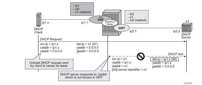
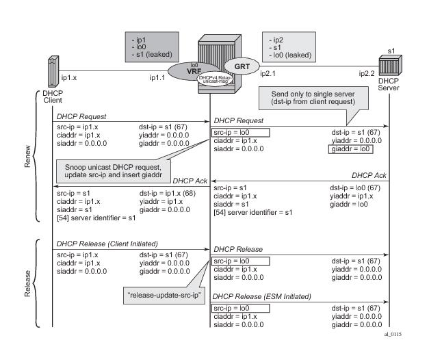
With the relay-unicast-msg command in the DHCPv4 relay on a regular interface or group-interface, it is possible to configure the gi-address of a DHCPv4 relayed message to any local address that is configured in the same routing instance. Unicast renewals are, in this case, relayed to the DHCPv4 server. In the upstream direction, update the source IP address and add the gateway IP address (gi-address) field before sending the message to the intended DHCP server (the message is not broadcasted to all configured DHCP servers). In the downstream direction, remove the gi-address and update the destination IP address to the value of the yiaddr (your IP address) field. By default, unicast DHCPv4 release messages are forwarded transparently. The optional
release-update-src-ip flag, updates the source IP address with the value used for relayed DHCPv4 messages.
For retail subscriber interfaces, the relay-unicast-msg must be configured at the subscriber-interface dhcp CLI context as shown in the Example 1.
The relay-unicast-msg function is not supported in combination with a double DHCPv4 relay (L3 DHCPv4 relay in front of a 7750 DHCPv4 relay with “relay-unicast-msg” enabled).
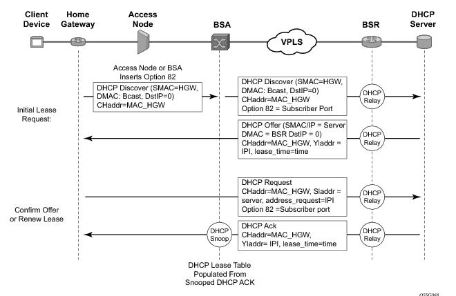
Option 82, or the relay information option is specified in RFC 3046, DHCP Relay Agent Information Option, and allows the router to append some information to the DHCP request that identifies where the original DHCP request came from.
When the circuit id sub-option field is inserted, it can take following values:
In the downstream direction, the inserted Option 82 information should not be passed back towards the client (as per RFC 3046, DHCP Relay Agent Information Option). To enable downstream stripping of the option 82 field, DHCP snooping should be enabled on the SDP or SAP connected to the DHCP server.
The trusted command is supported which allows the router to forward the DHCP request even if it receives one with a giaddr of 0 and Option 82 information attached. This could occur with older access equipment. In this case the relay agent would modify the request’s giaddr to be equal to the ingress interface. This only makes sense when the action in the information option is keep, and the service is IES or VPRN. In the case where the Option 82 information gets replaced by the relay agent, either through explicit configuration or the VPLS DHCP Relay case, the original Option 82 information is lost, and the reason for enabling the trusted option is lost.
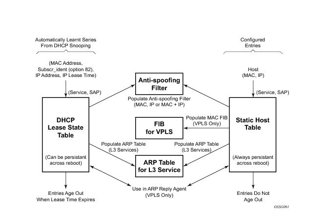
The DHCP lease state table has a central role in the BSA operation (Figure 17). For each SAP on each service it maintains the identities of the hosts that are allowed network access.
When the command lease-populate is enabled on a SAP, the DHCP lease state table is populated by snooping DHCP ACK messages on that SAP, as described in the
DHCP Snooping section above.
For VPLS, DHCP snooping must be explicitly enabled (using the snoop command) on the SAP and/or SDP where DHCP messages requiring snooping ingress the VPLS instance. For IES and VPRN IP interfaces, using the
lease-populate command also enables DHCP snooping for the subnets defined under the IP interface. Lease state information is extracted from snooped or relayed DHCP ACK messages to populate DHCP lease state table entries for the SAP or IP interface.
For IES and VPRN services, if ARP populate is configured, no statics ARPs are allowed. For IES and VPRN services, if ARP populate is not configured, then statics ARPs are allowed.
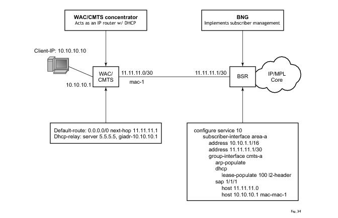
The mode of operation can be changed for DHCP snooping so that the Layer 2 header MAC address is used instead of the client hardware address from the DHCP packet for the DHCP lease state instantiation. This mode is selected by enabling l2-header in the lease-populate configuration command at the DHCP level. Because SR-Series routers do not have the ability to verify the DHCP information (both the
src-ip and
src-mac of the packet will be those of the previous relay point) anti-spoofing must be performed at the access node prior to the SR-Series routers. This mode provides compatibility with MAC concentrator devices, and cable modem termination system (CMTS) and WiiMAX Access Controller (WAC).
A configuration example of a cable/wireless network together with subscriber management is shown in Figure 18. The subnet used to connect to the CMTS/WAC must be defined as a subnet in the subscriber interface of the Layer 3 CO model under which the hosts will be defined. This means that all subscriber lease states instantiated on BSR must be from a “local” subscriber-subnet, even if those are behind the router, as there will be no additional layer 3 route installed pointing to them.
The prefix delegation options described in RFC 3633, IPv6 Prefix Options for Dynamic Host Configuration Protocol (DHCP) version 6, provide a mechanism for automated delegation of IPv6 prefixes using DHCP. This mechanism is intended for delegating a long-lived prefix from a delegating router to a requesting router, across an administrative boundary, where the delegating router does not require knowledge about the topology of the links in the network to which the prefixes will be assigned. For example, the delegating router can get a /48 prefix via DHCPv6 and assign /64 prefixes to multiple requesting routers. Prefix delegation is supported for the delegating router (not the requesting router).
A lease query by client-id as defined in RFC 5007, DHCPv6 Leasequery, is supported for Local DHCPv6 servers. For security reasons this must be explicitly enabled via the CLI flag allow-lease-query. The user identification option must be set to DUID (default value) for lease-query to work. Lease query by address is not supported. It is not possible to filter out leases with the link address, the server will always return all addresses for a client. The Relay Data and Client Link options are not supported and will not be returned.
With the relay-unicast-msg command in the DHCPv4 relay on a regular interface or group-interface, it is possible to configure the gi-address of a DHCPv4 relayed message to any local address that is configured in the same routing instance. Unicast renewals are in this case relayed to the DHCPv4 server. In the upstream direction: update the source IP address and add the gateway IP address (gi-address) field before sending the message to the intended DHCP server (the message is not broadcasted to all configured DHCP servers). In the downstream direction: remove the gi-address and update the destination IP address to the value of the yiaddr (your IP address) field. By default, unicast DHCPv4 release messages are forwarded transparently. The optional
release-update-src-ip flag, updates the source IP address with the value used for relayed DHCPv4 messages.
For retail subscriber interfaces, the relay-unicast-msg parameter must be configured in the
subscriber-interface>dhcp CLI context.
The relay-unicast-msg function is not supported in combination with a double DHCPv4 relay (Layer 3 DHCPv4 relay in front of a 7750 DHCPv4 relay with
relay-unicast-msg enabled).
The parameters that define the characteristics of the host will be represented by an LUDB host entry. The parameters in the LUDB entry can be unique for each individual host, or they can be shared for a group of hosts. In the former case, the identification field for the LUDB host entry must be host specific while in the latter case the identification field for LUDB host entry could be derived from DHCP options that are common to a set of host.
Subscriber host identification via LUDB is performed upon the arrival of the incoming DHCP messages on both, the access and the network side, while the host
instantiation and ESM string assignment is performed only during the processing of the DHCP ACK/Reply messages. In other words, if Python without the caching is used for subscriber host identification and classification (into proper service class by means of deriving ESM strings), the DHCP options required for host identification must be present in all DHCP messages – even the ones sent by the DHCP servers. However, DHCP servers are not required to echo DHCP options sent by the clients and relay-agents. Consequently, the missing options from the server side would cause the subscriber host instantiation to fail.
To remedy this situation and cover all deployments models (even the ones where the DHCP options are not echoed back by the DHCP servers), a caching mechanism is introduced whereby the results of the Python processing on ingress access are locally stored in 7x50. This will ensure that the information about the subscriber host is readily available when the DHCP packet from the DHCP server arrives. Furthermore, since we already have the cached information, no additional Python processing on the network ingress is needed.
The caching is performed in a DHCP Transaction Cache (DTC), which is accessible to Python and to the EMS module. Python will write the result of its processing to it and the Enhanced Subscriber Management (EMS) module within 7x50 will be able to access those results.
The cache entries are relatively short lived, with the lifetime of a DHCP transaction.
DHCP transaction is defined as a pair of DHCP messages that have the same DHCP transaction-id number (<Discover, Offer>, <Request, Ack>, <Solicit, Advertize>,<Request,Reply>, <Renew, Ack>, etc).
alc.dtc.derivedId — A read/write (from the Python perspective) string to store the LUDB lookup key for subscriber host identification. This key is derived from the contents of the packet. This string will be used as a
match criteria in LUDB. The derived-id can only be used when the lookup is performed in ESM. If the LUDB is attached to the local DHCP server, then the lookup based on the derived-id cannot be performed as the DHCP server has no means to derive such an ID from the DHCP message.
alc.dtc.store(key,value) => the operator can store any data he desires in one or more entries. The key can be any arbitrary string (printable ASCII characters), up to 32 bytes in length. The value part is ‘unlimited’ (memory permitting) in size.
alc.dtc.retrieve(key) => retrieve data from the DTC. The key must be an existing key, which is a string consisting of printable ASCII characters, up to 32 bytes in length.
alc.dtc.setESM (key-from-below, value) => store data that is used by ESM. This data is write-only.
The keys will be predefined (only these can be used) and are shown in
Table 10. These keys are read-only static variables.
alc.dtc.ipAddress = “192.168.0.10” — This is performed through the following ALU API:
alc.dtc.setESM(alc.dtc.ipAddress,’192.168.0.10’). The DTC logic then parses this variable and converts it into appropriate format for consumption by ESM code.
debug router <
router-id>
ip dhcp --> Enable DHCP debug on Layer 3 interfaces, including subscriber-interfaces.
debug service id <
service-id>
dhcp --> Enable DHCP debugging on capture SAP.
The virtual-subnet command in the
sub-if>dhcp context allows the system to snoop and record the default router address in DHCP ACK messages for a DHCPv4 ESM host. The system can answer or traceroute request even if the default router address is not configured on the subscriber-interface.
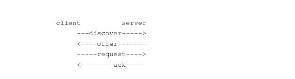
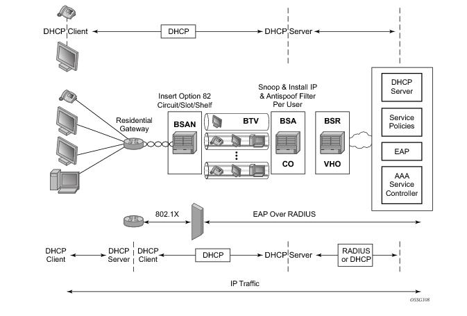
The use of DHCP in the provider market is a growing trend for managing subscriber IP addressing, as well as supporting newer devices such as IP-enabled IP phones and set-top boxes. The majority of subscriber management systems rely heavily on RADIUS (RFC 2865, Remote Authentication Dial In User Service (RADIUS)) as the means for identifying and authorizing individual subscribers (and devices), deciding whether they will be allowed access to the network, and which policies should be put in place to control what the subscriber can do within network.
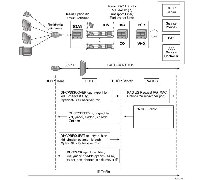
Figure 20 displays a typical DHCP initial boot-up sequence with the addition of RADIUS authentication. The proxy DHCP server will interface with downstream DHCP client devices and then authenticate upstream using RADIUS to a providers subscriber management system.